
<< Part 2: Coupling || Prologue: Cost >>
So now you’ve got freshly painted coaches with closer coupling. Now I’m going to show you how to make some gangway connectors to really complete the look!
Here’s what you’re going to need to make:

A concertina’d strip of paper or card to fit between your coaches to emulate this…

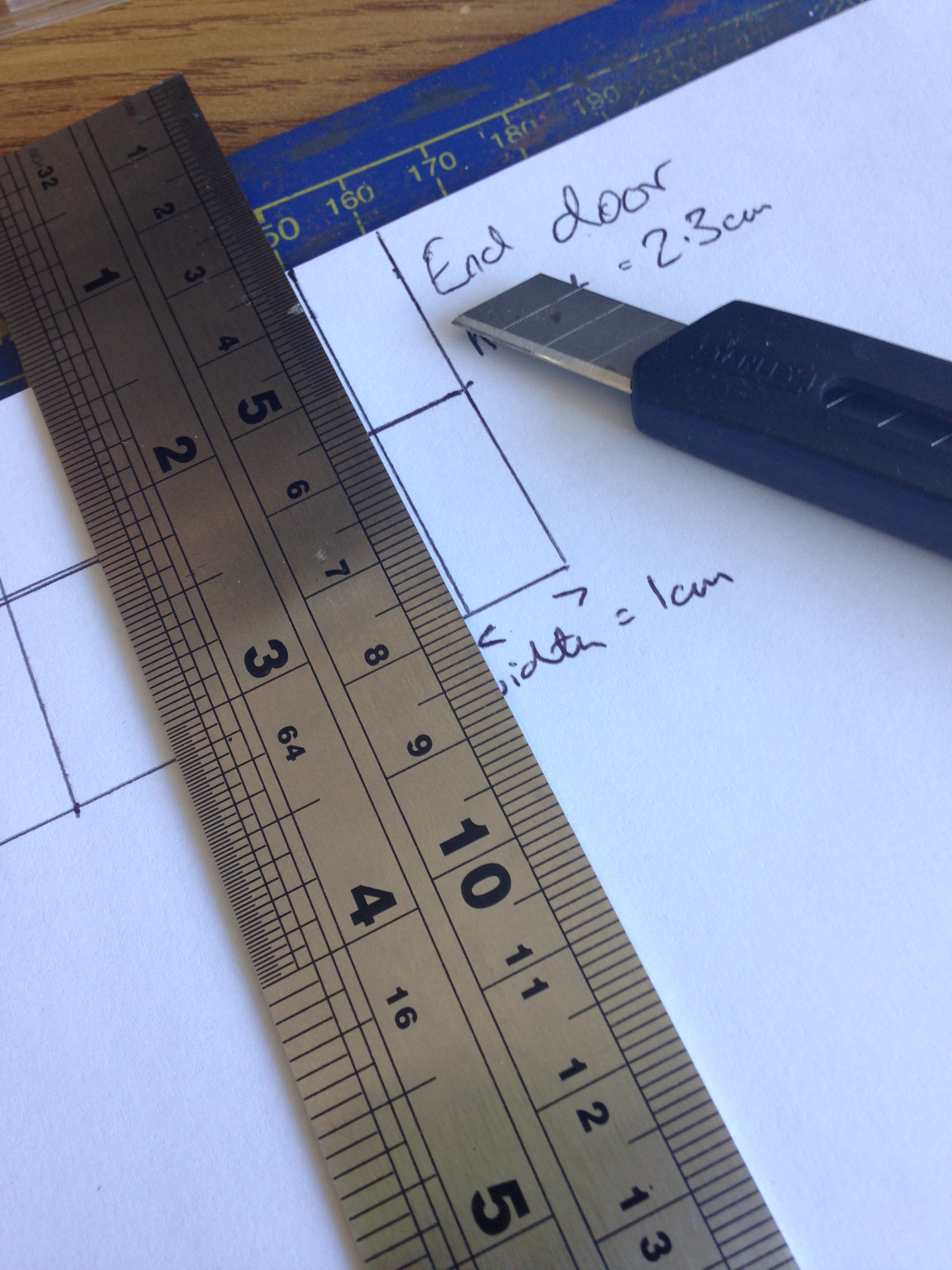
First measure the doorway of your coach. You’re going to want your gangway to be slightly smaller than the plastic frame. For the LMS coaches that’s about 1cm x 2.3cm.
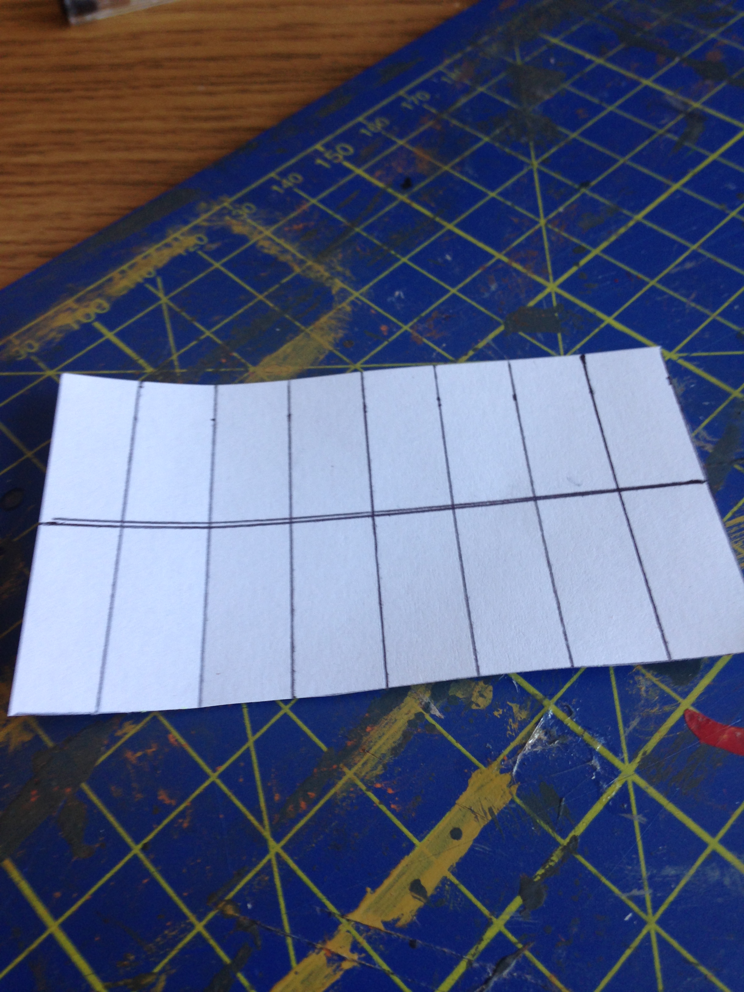
Draw out a grid like this using some cheap printer paper to make a prototype….

The number of boxes or folds you make is entirely down to the coach you’re fitting the connector to. Some trial and error will be required but I’d recommend starting with 8 boxes across. To make the concertina work you’re going to need two rows of however many boxes you choose.
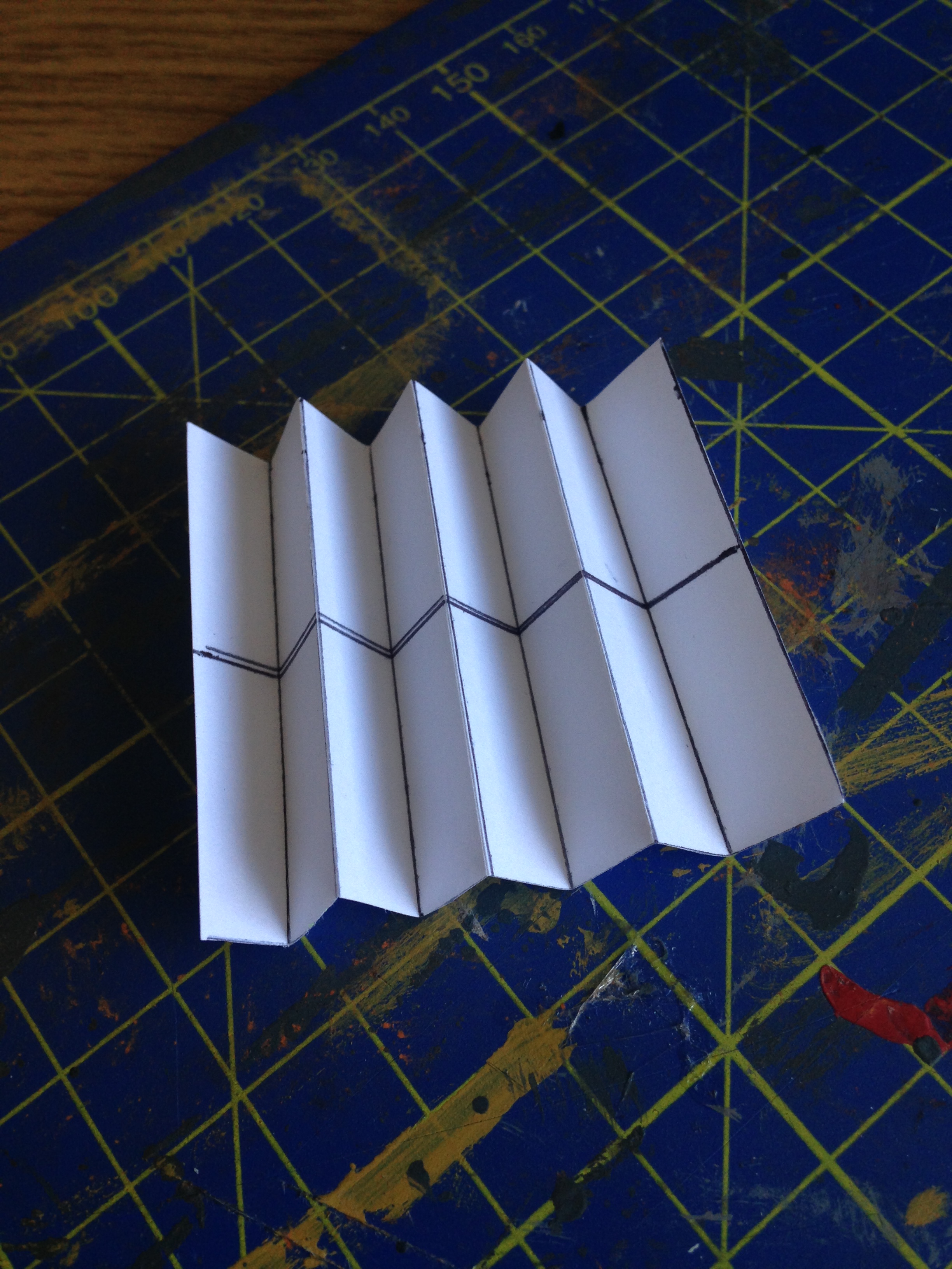
Next, lightly score along the vertical lines. This will help you when folding the paper…
Cut this out…
…and fold…
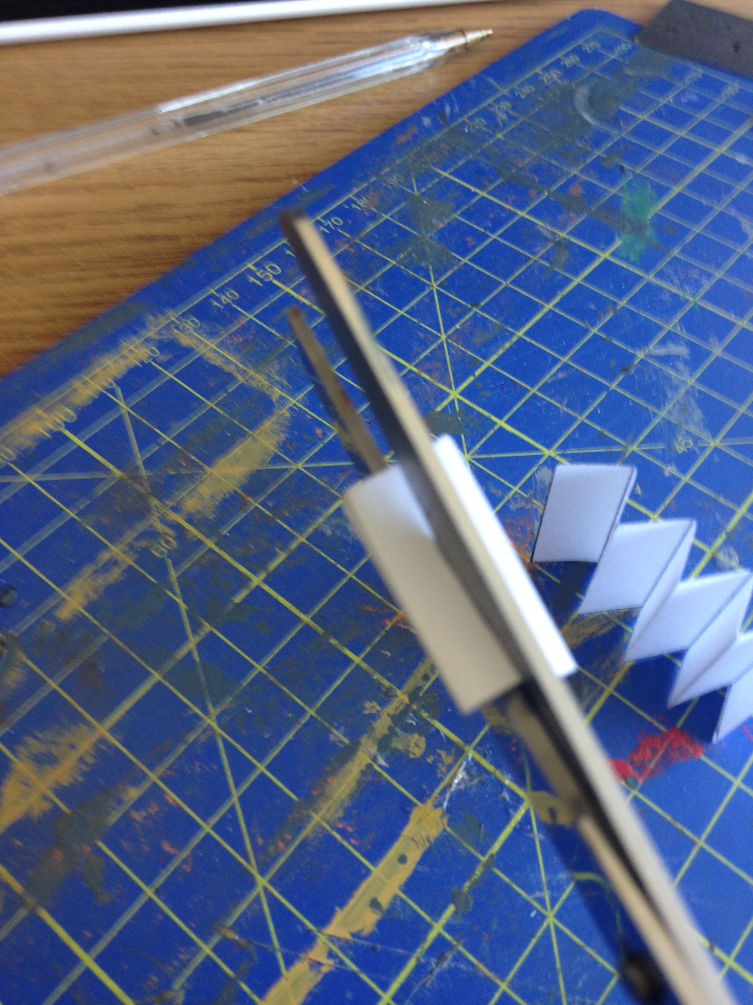
Now cut your two rows in half…

With your paper folder up, make an incision just over half the height of the connector as shown:
Repeat this with your other row and carefully slot the two together..

This is very fiddley! But eventually you should end up with something like this:

Using Blu-tack, fix the gangway connector to the doorways of two coaches. The concertina will expand and compress whilst traversing curves and inclines. If you’re happy with the way it looks, try it out with black paper, or thin card…

I’ve actually gone further still…

Instead of a full concertina of 8 panels, I’ve made two separate 4 panel concertinas for each coach. I’ve then fixed a piece of plasticard (this can be painted later) to each end to complete the look…

When coupled together the concertinas compress to look like a complete gangway. They will also rub together whilst traversing curves and gradients. I found this to be much more reliable and easier on the eye than using a complete connector of 8 panels which would often twist and jam in unfavourable positions causing derailments. (Especially with thicker paper).
Here’s how they operation looks on a 2nd radius curve with an incline:
At the beginning of the curve you might find the gangways move too far away from each other for your liking. I’ve settled on this compromise as the reliability is excellent whilst still looking the part the rest of the time.
Again, always test your prototypes, and test them in a variety of scenarios and movements.
Once you’re happy, paint the plastic black and there you have it…
…a complete rake of improved coaches!
For more pictures and a word on costings, head to the prologue.

[…] 1: Painting Part 2: Coupling Part 3: Gangway Connectors Prologue: […]
[…] << Part 1: Painting || Part 3: Gangway Connectors >> […]
very helpful and economical, just need time and patience to get a good result