Langstead – Episode 15: Test Runs

Following on from Episode 14 I now have all the required extra bits of track to complete the new outer oval.

IMG_2193

Here’s a rather suspect panorama (thanks to iOS7) of The Mainline with the additional oval.

It’s hard to spot in the picture above but at the rear of the layout the oval runs on the old boards and at the front it drops down and runs on the new woodwork. This means either side must accommodate a modest gradient to raise and the lower the line between the sections. Continue reading

Langstead – Episode 14: Extensions

The Mainline as of August 2013

The Mainline as of August 2013

I promised myself that once I moved into my new flat I would in someway look at expanding my layout, now known as ‘The Mainline’ for sake of giving it a fancy title for this new site.

Possible areas to expand into marked in yellow

Possible areas to expand into marked in yellow

Now, I’ve not got acres of extra space to work with: Either side on the left and right there is perhaps 10-12 inches of spare room between base board and wall. Nonetheless I think it’s just about enough to think about an expansion in some way.

Option 1: Split and Insert

Option 1: Split and Insert

First idea is to separate the two boards, move them both into the yellow zones and insert a new board in the middle where the red line is. You may remember that my original design factored in this potential method for expansion.

No major track work will need to be done, it’s just a case of adding another straight to each oval. It will be slightly fiddly to plug the scenic gap but nothing too difficult. The major problem with this plan is the two speaker stands at the back of the room. Currently the baseboard nestles snugly in between them both and are flush against the back wall maximising space. If I were to separate the two boards to add a new piece I’d either have to move the speaker stands completely, or, bring the entire layout forward (and off the back wall) to accommodate the expansion. I don’t like the sound of either of those two plans.

Option 2: Expand on the left hand side only.

Option 2: Expand on the left hand side only.

Second idea is to expand in one direction only. In this scenario a terminus station or yard could be considered for scenic and operational interest. I’ll be honest, this was my preferred idea for quite sometime… I’ve since discovered that I much prefer sitting back at my desk (where these pictures are all taken from) simply enjoying running various trains. I’ve found I’m much more likely to do this rather than sit at the layout itself and make lots of complex operational changes… after all, that’s what Salford Chapel is for… The Mainline has become much more an outlet for running trains whereas Salford Chapel is becoming the more detailed ‘model.’ Therefore, maximising the number of trains I can run would be priority in this expansion project. The station or yard option above would allow me to switch stock around however I’d definitely have to look at motorising points so I’m not constantly leaning over the entire layout all the time. (I’ll admit this gets a bit irritating).

Option 3: Elevated Line?

Option 3: Elevated Line?

Option 3 is a bit… out there… Build a completely new oval, elevating it above the rest of the layout. I really like the idea of adding height and it’ll mean I’ll be able to run a 3rd train at any one time, but logistically I really don’t know where to begin in making it a reality. Far too complicated.

Option 4: An outer oval.

Option 4: An outer oval.

Same as Option 3, but less wacky. There’s a relatively unused siding at the back of the layout. I could essentially develop this into another full outer oval, expanding in all directions but hopefully in such a way that I won’t have to move the speakers or take up too much room at the front of the layout. Now we’re talking!…

The Outer Oval

The Outer Oval

Ignore the fact there’s some track missing from the above layout on the inner ovals, this is because the free version of the AnyRail5 software I’ve used only allows 50 pieces at any one time. The green piece of track at the bottom will need to be lifted to make way for the outer oval curve. Overall the layout will expand only 3 inches at the sides and 3 inches at the front, but will allow the operation (and interest) of running a 3rd train.

Now I could add braces to the underside of the original baseboard to support a 3 inch strip of wood all the around the layout. However, I thought it would be far easier to buy completely new boards, slightly wider than the old ones, to accommodate both the new oval AND the old boards themselves…

Lifting Track

Lifting Track

First job was removing the redundant siding at the back of the layout. Old ballast was chiseled off and the section of track lifted. I’m not worried it left a bit of a mess, I’ll model over this in good time.

Deforestation...

Deforestation…

...Is required

…Is required

Corners of the board were sawn off to make way for the outer oval.

Changing Legs

Changing Legs

Legs and leg plates were removed from the old board and added to the new ones. See Episode 17 for this process!

Old on New

Old on New

The old boards were then laid on the new ones now clearly showing where the outer oval will eventually go. It’s worth noting that they are still in two parts – to enable dismantlability, and still leave room for the speakers to remain in place at the back of the room. There’s also a height difference between old and new which will add some much needed depth to the layout. Gentle gradients will rise and fall from the old siding at the back of the old boards to accommodate this.

Buildings reassembled!

Buildings reassembled!

I’ll be off to ebay now to get some more track! Stay tuned for results soon.

– Andy Carter

Langstead – Episode 13: The (Semi)-Permanent Way

There hasn’t been an update for a while. Things were put on hold until I moved flat (which recently occurred). So rather than talking about wagon weathering as suggested in last episode (and I will do soon, I promise), I will be talking about moving flat and how this has affect my Main Layout and Salford Chapel.

If you want to remind yourself of some of my original objectives, especially with reference to my Main Layout, you can do so here. The main challenge I originally faced was storability, and maximising relatively low amounts of space in my old flat. I’m rather pleased and excited that this requirement has now changed and I have much more space at my disposal.*
*This was a requirement that the new place should have a facility for me not to have trains in the living room as dictated by Leah…
I now have something of an office/studio/workshop, whatever you want to call it (perhaps it should be called Man-Room) dedicated to, and amongst other things, my layout(s). 
This is all well and good, however at my old flat the boards simply went on the extended dining room table. Now I don’t have anything to put them on…
My original objective of Storability is now less important. In fact the layout can now be fitted on something semi-permanent. – I’m always reluctant to make something fully permanent in case I change my mind about something, want to move things, or actually do require space again in the future.
So I had a couple of possible solutions…
Buy a frame: A quick search of Google suggests that it is completely feasible to purchase just a frame for model railway baseboards. These are more on the expensive side and there’s a feeling of out sourcing the problem to someone else rather than coming up with a better alternative on my own.
Possible idea – frame with folding legs. (Imagine without baseboard).
Build a frame: I could build it myself. A bigger issue with a frame is it’s rather inflexible and more permanent than I’m willing to make it. I’d have to therefore factor in folding or detachable legs into the frame equation making things liable to expense and complication. (I really don’t like complication). 
Now here’s an idea – IKEA do various cheap tables, the beauty of these is they have detachable legs. I know this because I’ve got a desk in this format. They’re simply made up of a disk – mounted to the wood, then a pole screws into the disk to provide the leg. Simple! The other thing I could do is buy some trestles and be done with a frame completely, but I still think we can go one step simpler…
What about just buying the IKEA legs and attaching them straight to the baseboard itself…
The legs cost £2.50 per pack. In a pack you get one leg, one mounting disk and the necessary screws. So we’re looking at £20 for 8 packs (remember I have 2 separate boards so it’s 4 legs per board), which considering some of the alternatives is the most cost effective simple solution.
One minor setback is the screws that come as standard (right) are far too long for my board. I popped into B&Q and purchased some shorter ones (left). You’ll want to get self-tapping screws, which will ram themselves into your baseboard far easier than normal ones. The alternative is to drill pilot holes (a hassle). 
I’ve laid my board track side down on a blanket on the bed. This will cushion the force I will need to apply to screw in the metal disks for the legs and ultimately protect the track. Hopefully you’ll not have to do this if you’re building your base-board-IKEA-solution first. 

First decide where you want to place the disks. If you’re starting from scratch you can plan this hole operation from the start with more precision. Because I’m doing this backwards and my track is already laid, I want to avoid attaching the disks bellow points – where I may want to add motors, wiring and things that require drilling at a later date. This optimum location was about 6 ½ inches from each edge. I then measured and marked out each disk position. 
Using a bradawl, score out where you want to insert screws. For some reason I couldn’t find bradawls in B&Q. But really all you need is any old sharp spike. Fortunately I found this…
A TWIST GIMLET. Possibly the most exiting name of any tool you’ll ever find. It did the job just as well. 
I’ve since learned that it’s actual job is to drill small pilot holes in wood by hand. And, well that’s what I’m trying to do. 
Next, make sure the disc is lined up with your pilot holes and simply pop in the screws. Now my baseboard is ply wood, which accepts screws, nails and twist gimletage with relative ease. If you’ve got a denser wood it might not be so easy. Even so, you’ll need to apply a fair bit of force for the screw to take. I found a mixture of using my electric screwdriver and a ratchet screwdriver were best for the job.
After that attach the screw in leg to the disk…
…and repeat…
And that’s it. Nothing to it really!

I’ll be able to detach the legs and store the boards as before should I need the extra space for guests or need to move the boards at a later date. 
And there both boards sit in Man Room with aforementioned glass display cases for rolling stock!
In the meantime, Salford Chapel (the shelf layout) takes a spot on an actual shelf…

Langstead – Episode 12: Rails

There’s been a lot of talk about Salford Chapel and as a result I haven’t posted on my Main Layout for a while so it’s time for a couple of updates… 
A Minor Derailment 
I’m not going to lie. You’re going to get derailments on your model railway… Mimicking real life? Well you’d hope not, but let’s not forget we’re dealing with moving parts a 76th of the size of their real life counterparts. It’s bound to happen every now and then. I’ve even been at exhibitions where I’ve seen it occur, so don’t worry it – it happens in the pros… You’ll quickly find out that there are either certain types of rolling stock or certain areas of track that potentially cause frequent problems. There are usually some common causes. 
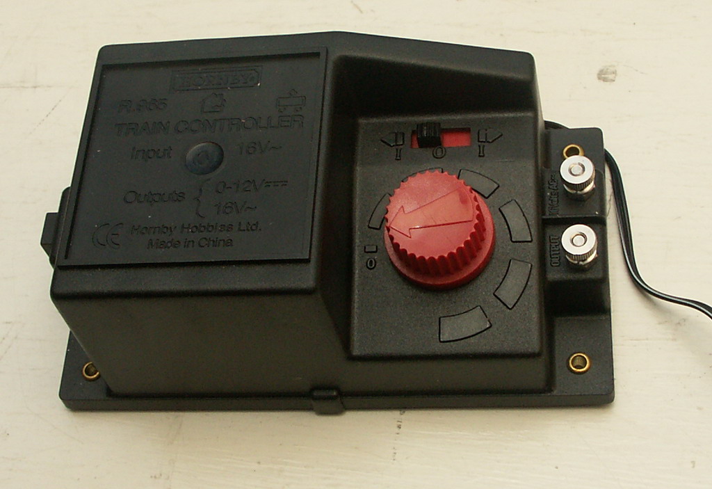
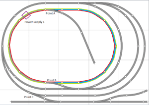
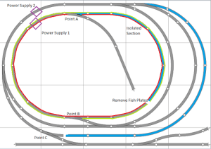
Above is an example of a the common Hornby Point (R8072/3). Common because the curve on it fits the 2nd radius oval standard set by Hornby and thus slots easily into most layouts. (Here you can see them littering my layout). The problem with these are they aren’t really designed for trains to run over the curved alignment at (what I’d consider to be) mainline speed. 
You’d be better off using this, the Hornby Express Point. Named aptly for more appropriate line switching at higher speeds. For realism they look and work a lot better, but for the space conscious modeller, myself included, they take up more room and do not fit so nicely into the design of your layout. 
Why do the standard points cause derailments you might ask? Well, certain rolling stock have a tendency to jump the guide/check rails and/or frogs – but I will come to this shortly.
99% derailment issues will happen over points but there’s usually other factors involved…
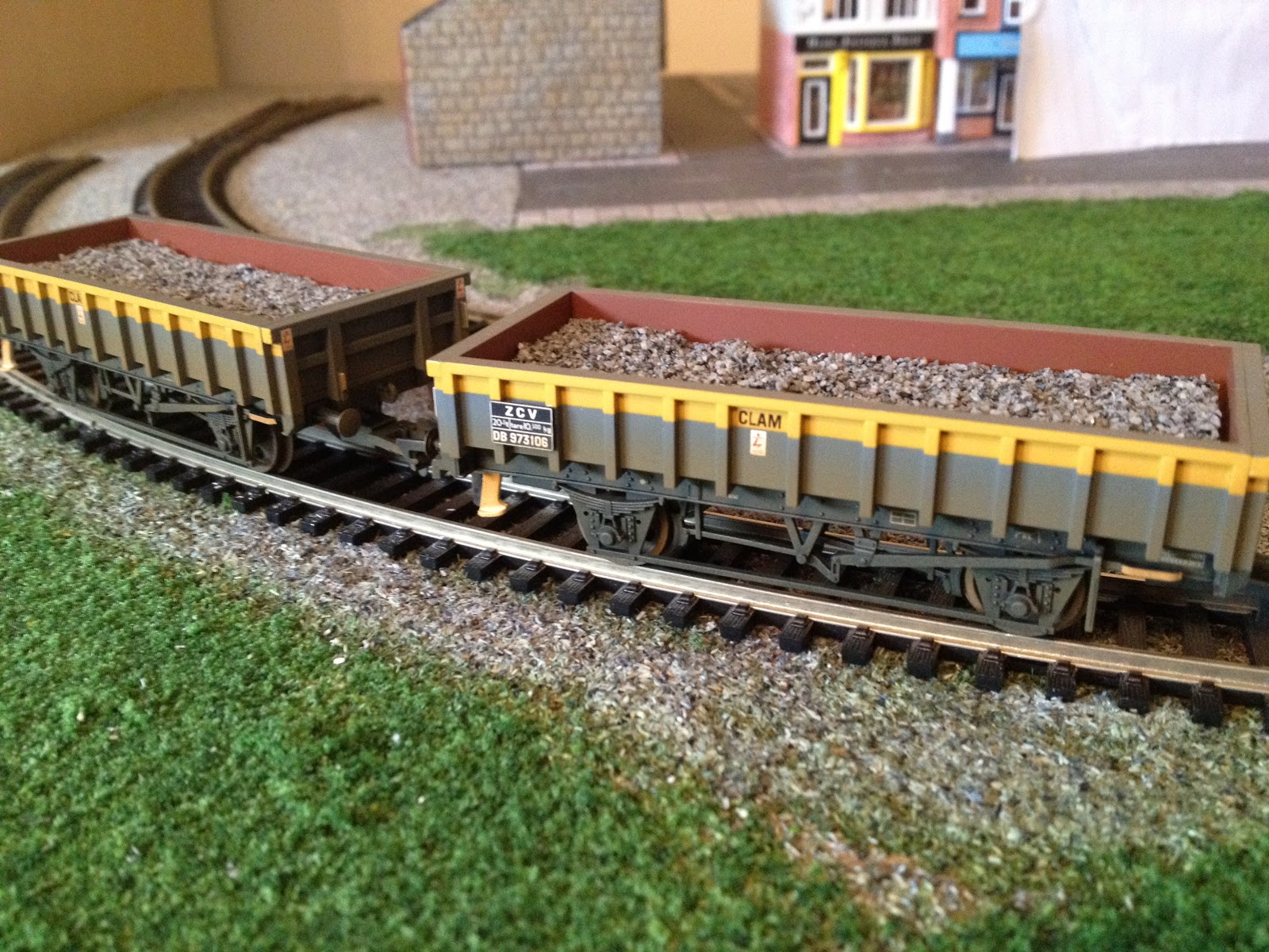
Rolling Stock Wheel Base: 
Remember these? Well I have a set of three, and in certain scenarios they are a real problem child going over the aforementioned points. Being pulled – they’re not a problem – and I think this is because the loco or next wagon is providing some guidance. However when shunted/pushed the lead wheels tend to slip up and over the frog (this is the ‘V’ shape made by the adjoining rails). 
Different wagons are fine over the same stretch of track in the same conditions. It just so happens that the wheel base of these wagons are such that they are derailing in this scenario. Not a lot you can do in terms of altering the wheel base but there is a solution which I’ll get to shortly.
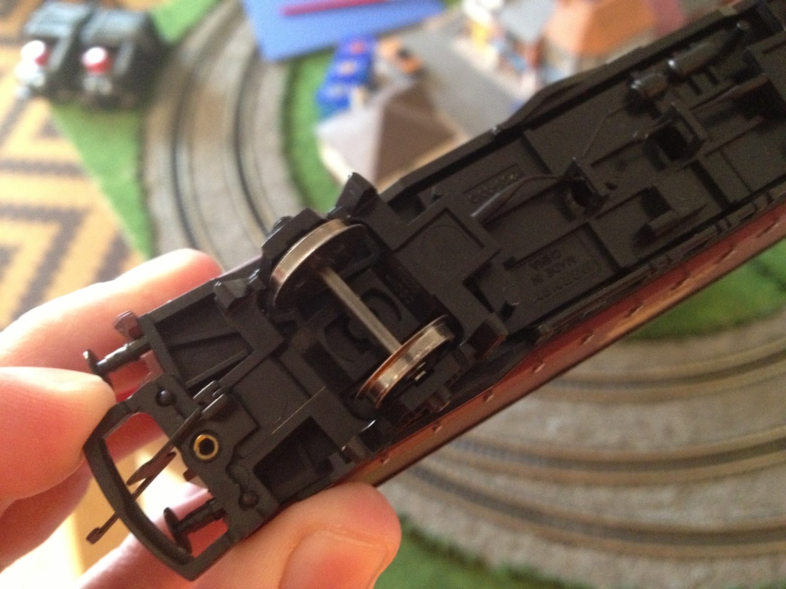
Bogie Type:     
The Parcel Van pictured above has only 2 wheels at each end. In this example the axel is fixed, and this van causes me no problems what so ever. I do however have a version of a similar sized van where the axel is allowed to pivot. Just like a 4 wheel bogie setup on a coach or loco. 
This is just asking for trouble.
These unusual 2 wheel bogies slip over points regardless of push/pull formation and regardless of direction. I’m not sure if such vans exist in real life? It doesn’t appear to be a very good idea. Hornby seemed to have reverted to fixing the axels on later models.
My suggestion if you have any offending vans would be to run them at the rear of your train. I’ve also noticed they actually prefer running at speed when being pulled. More tension in the coupling and a more precise guidance perhaps. They certainly don’t work very well being pushed at speed that’s for sure. 

Coupling Mismatch:
This is a new problem. All Hornby models of old had the same sized coupling components. Nice big chunky hooks  and bars with plenty of give.
Newer models though (and those of different brands) are fitted with these daintier versions. Smaller hooks and smaller catchment areas. The result means a closer coupling and better realism. Using these new couplings together, no problem. There’s a slight flex in the joint for running on curves and they work perfectly. Problems start to arise when you use the old and new type together. The larger hooks tend not to fit in the smaller catchment area, and the smaller hooks often unlatch from older couplings. 9 out of 10 times though, you’ll get it working, however be aware that occasionally whilst being shunted (and not surprisingly over points) the couplings may knock each other in ways that will derail your wagons. 
So now we know some derailment causes what can you do about them? 
Well, I’ve already outlined a few pointers. Stay away from the weird 2 wheel bogie vans, try to couple like for like wagons and be aware that some stock will cause you problems. I’m not going to say, ‘Don’t buy X and Y they always derail’, because chances are elsewhere on your layout they’ll work fine. It always seems to happen in those really specific places. 
Now, if those places are the standard Hornby (Or Peco by the way) point – here’s a potential fix. 
It just so happened that a new loco I got for Christmas was frequently derailing at these set of points. This was bemusing because up until now these points hadn’t caused me any problems. Unfortunately this will almost certainly happen to you. One fullproof set of points for all your rolling stock will inexplicably be a problem for that certain one train, coach or wagon!
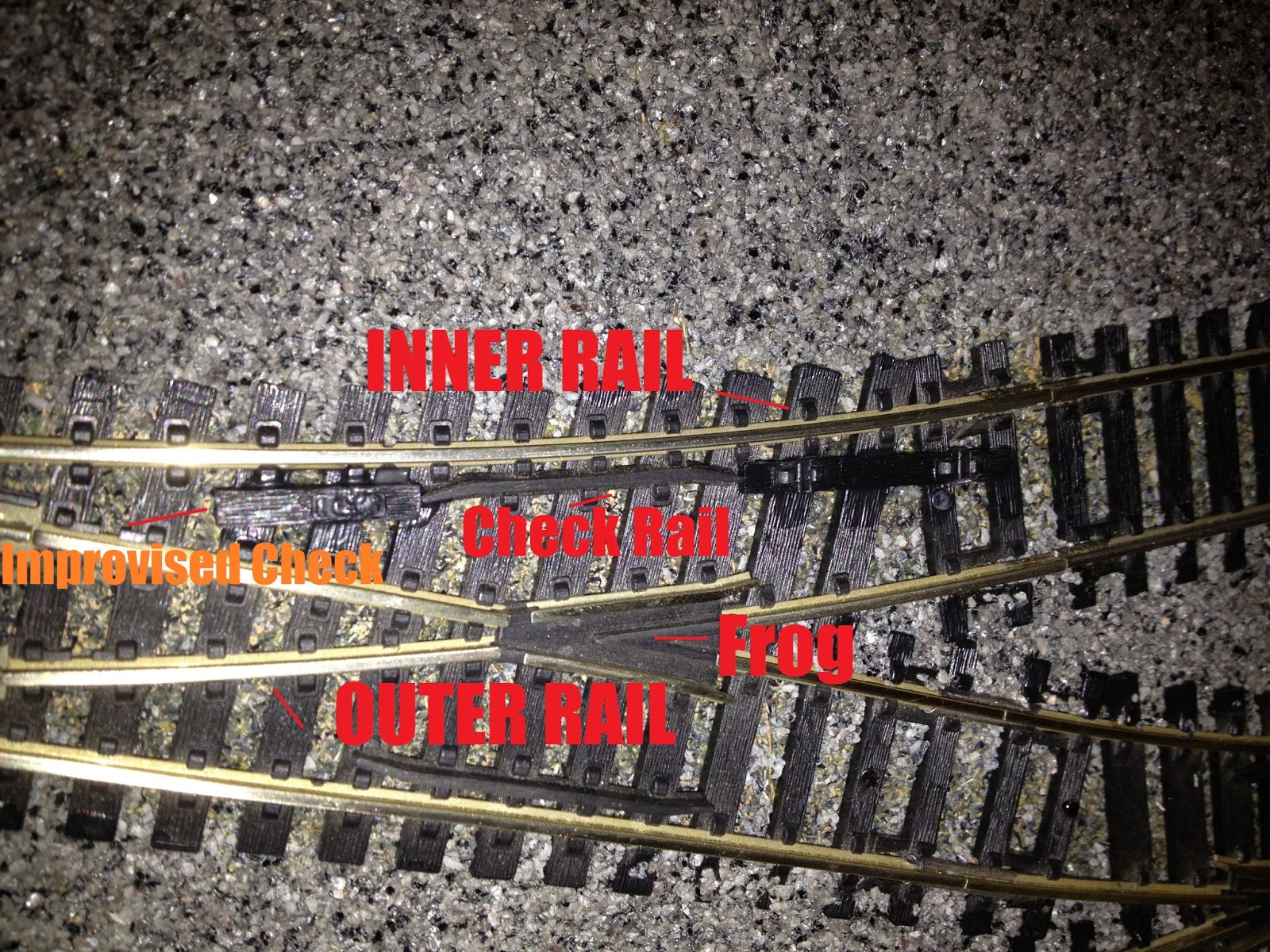
(For the following explanation imagine loco running from right to left on the curved allignment). 
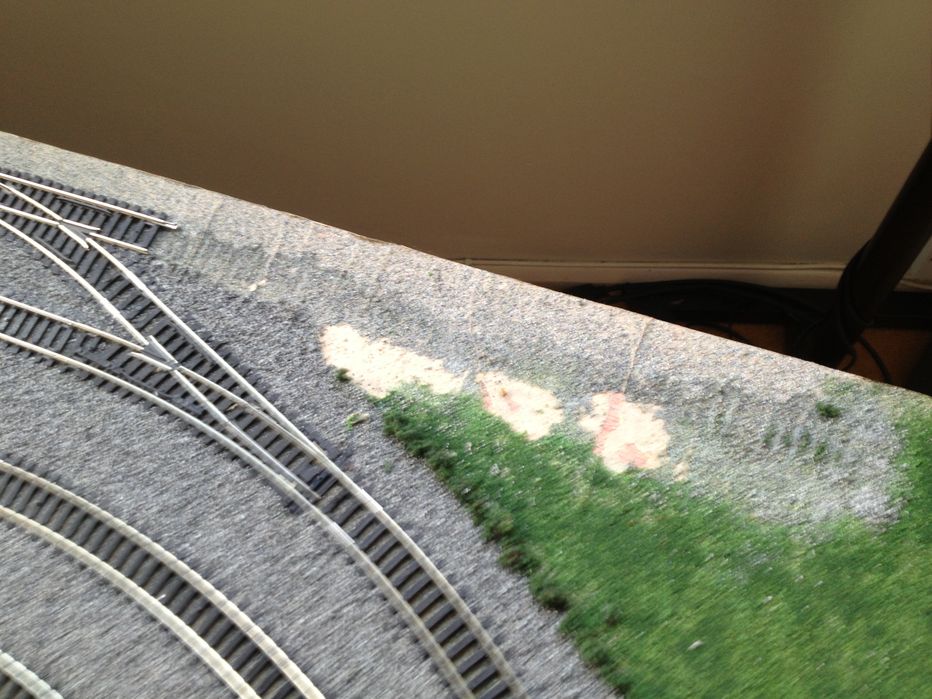
On closer examination I noticed that the wheels of the train appeared to be coming astray just after the frog on the outer rail. It was only until I observed the other side of the train on the inner rail did I realise that the check rail just wasn’t doing its job properly. 
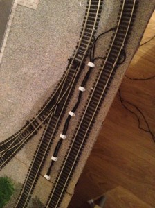
To solve this I improvised extending the check rail by introducing some unused sleepers either side. 
Success! The sleeper, now acting as a further check rail, pulls the wheels back on course. I’ve since read up on the internet about hornby point derailment cases and learnt that older hornby points (of which I had) were known to have smaller check rails. Newer ones have been improved but if you’re experiencing derailment issues why not try this!
I applied the same method to other problem points and this even solved the issue created by the odd wheel base wagons! 
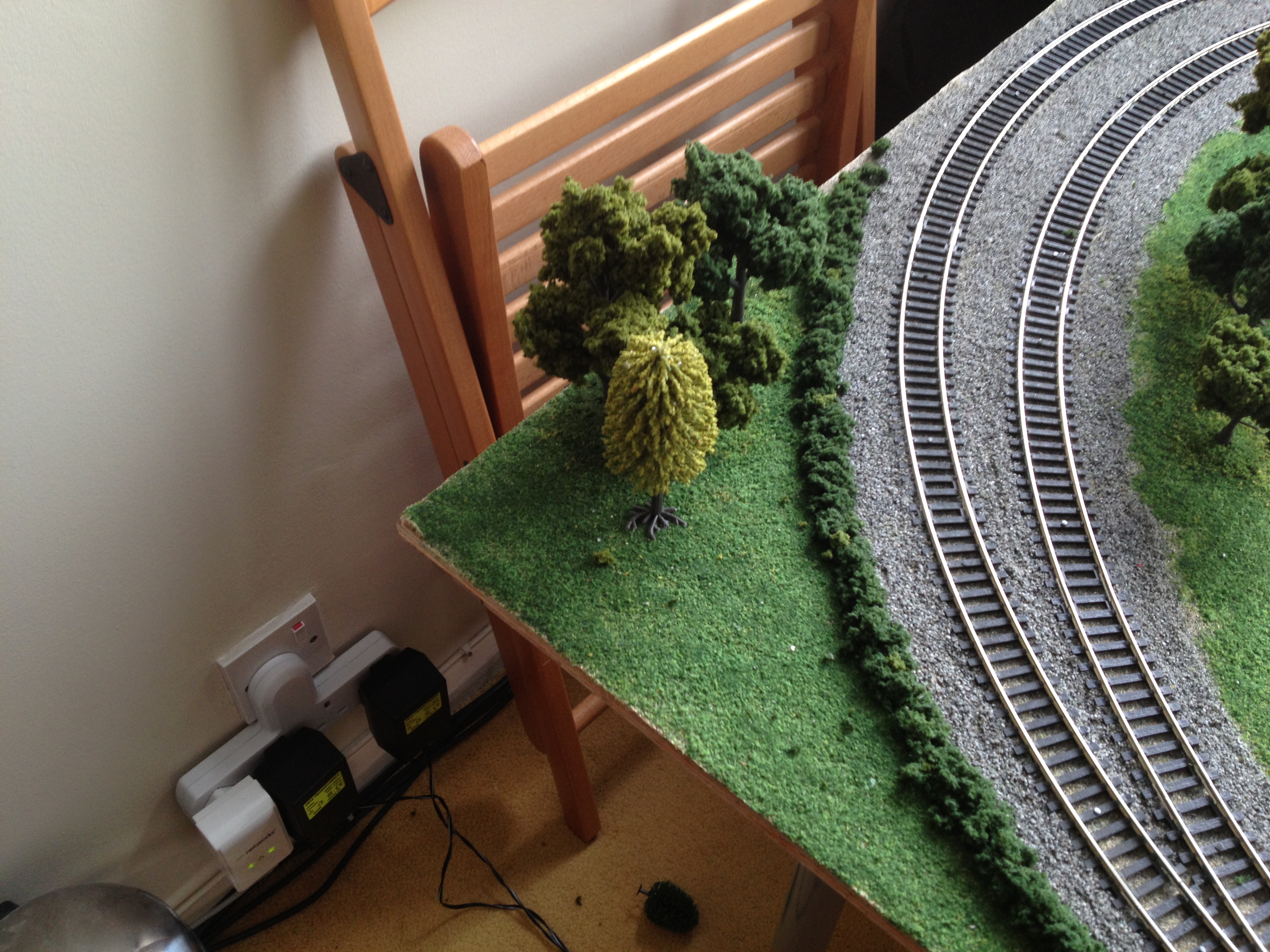
Completing The Roadway
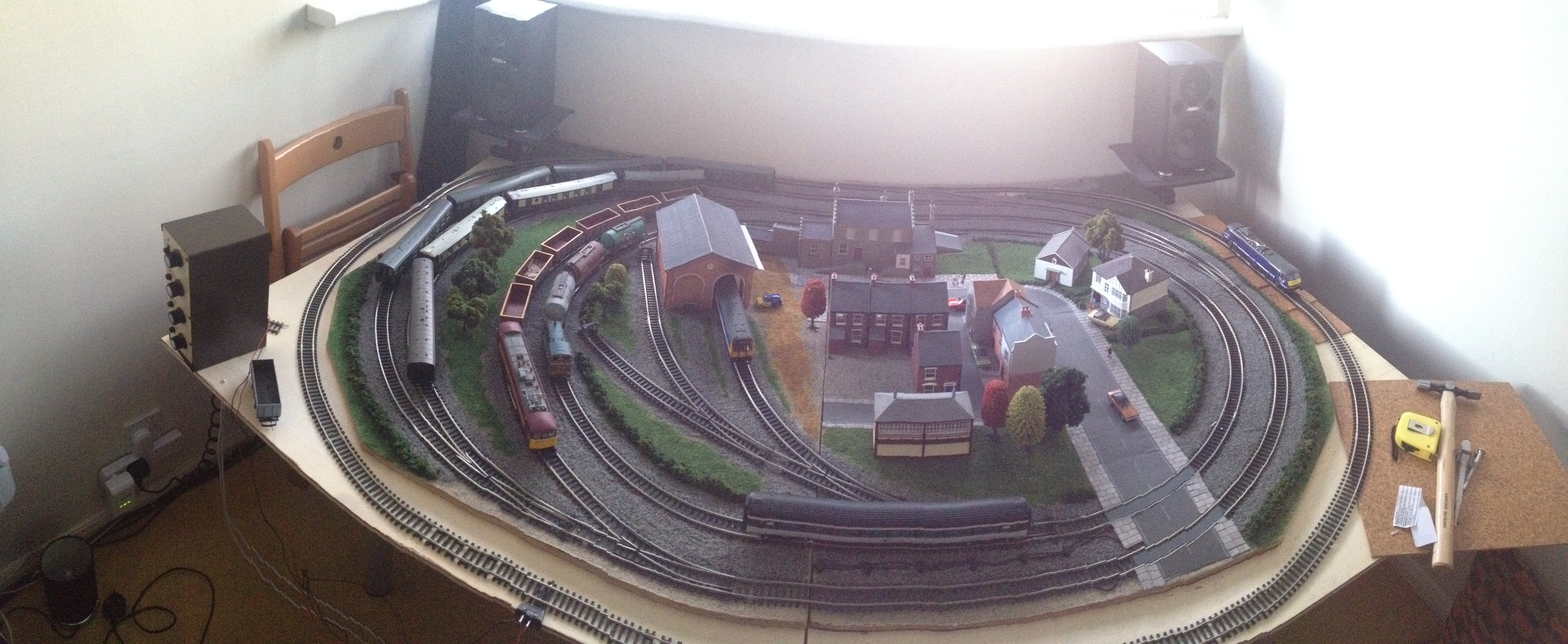
Elsewhere on my layout this is what I’ve been up to…
You may remember from previous episodes that I left a gap in ballast laying to leave room for a level crossing. Well now it is time to plug that gap.
Most good model shops will stock thin cuttable plastic (normally in white). These come in a variety of flavours ranging from piping to girding and from stairways to thin strips. 
They also do fairly large sheets, and this offering from Evergreen I’ve have cut to shape the curvature of the track and stuck down with superglue. 
If you’ve not opted for one of the many pre-made level crossings out there and you are planning a level crossing on a straight section of track, this will be a pretty simple procedure of marking, measuring and cutting. I, however, have made things difficult for myself by locating the crossing on a curved section of track. This was initially done to save sections of straight track for points as space was at a premium. 
After a few failed attempts of cutting the plastic by simply winging it I came up with a solution…
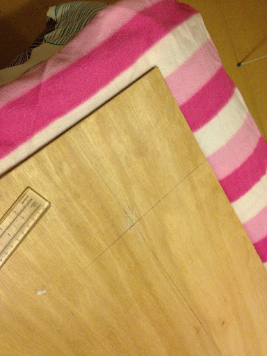
Take a spare piece of track that matches the curve radius you are trying to mark out. Turn it upside down and then you can mark where the rail touches the plastic. This will in turn create three pieces: One piece to fit outside of either rail and one piece to fit inside (this will need to be trimmed so the wheels do not touch it). Put these in place and keep making sure a variety of rolling stock will run over it with no faults. Once you’re happy you can stick it down as I have above. I’ve then started to stick roadway and pavement down.
I opted to paint the centre pieces rather than cut out further fiddly pieces of roadway. 
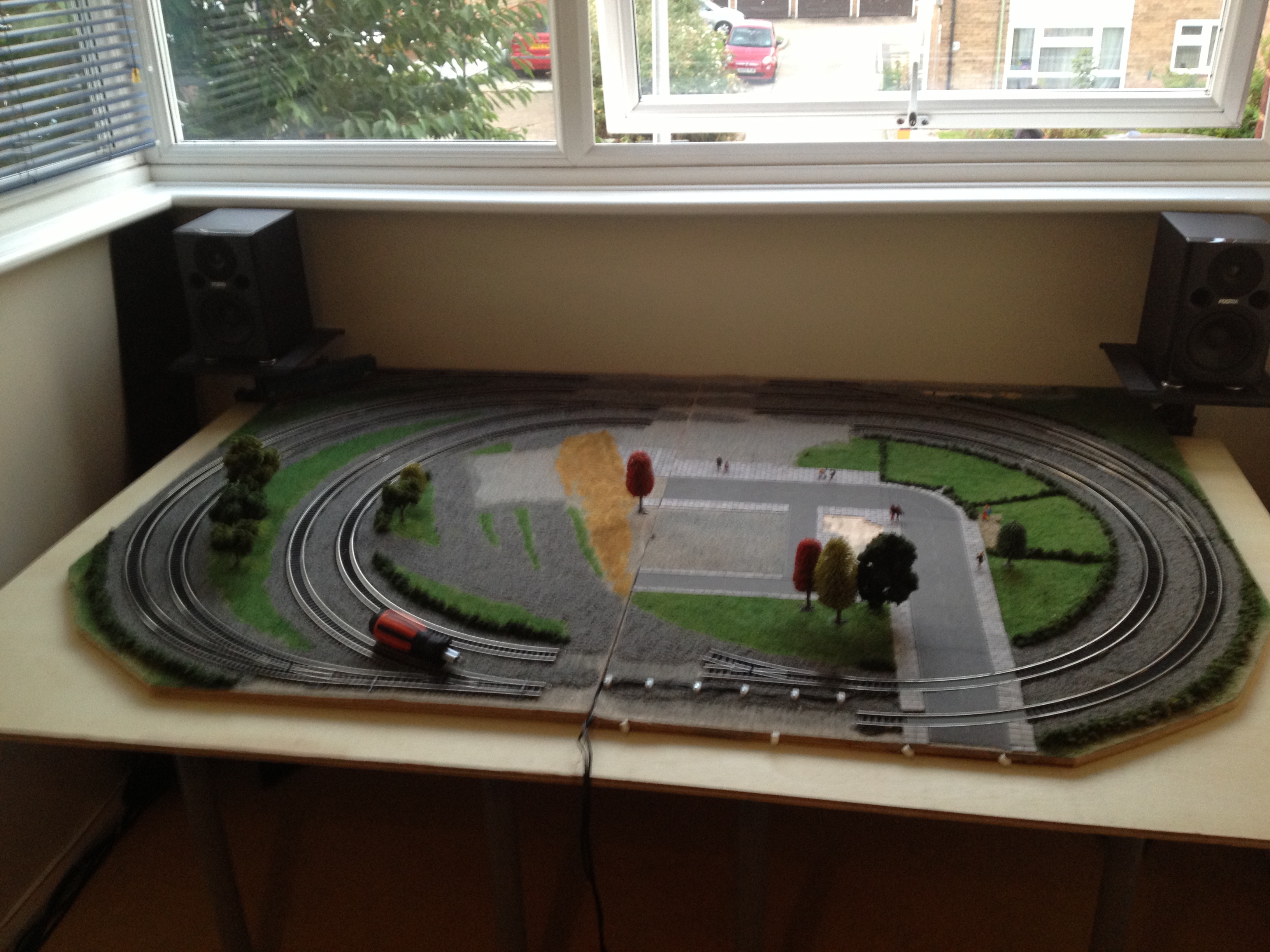
The finished article both without… (The gap in the pavement by the way is to leave room for the power supply wire).
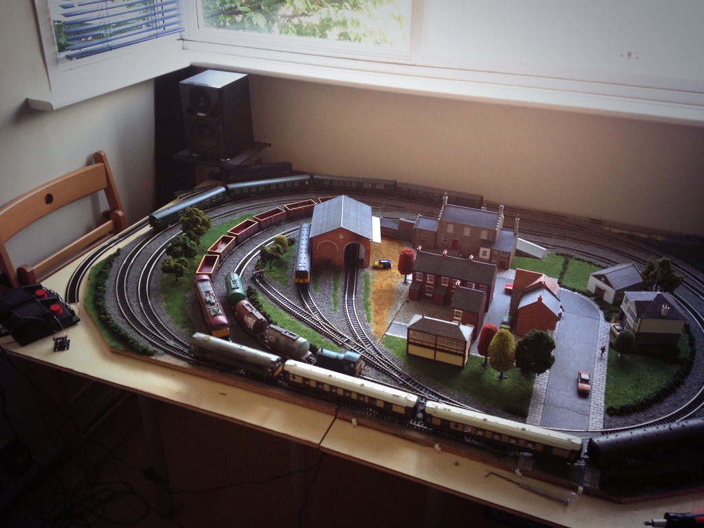
And with train.
See those grubby looking wagons in that picture? I’ll get on to some weathering techniques next time!… Stay tuned…

Langstead – Episode 11: Powerrrrrrrr

As the great Jeremy Clarkson once said, ‘Powwwweeerrrrrrr.’
Back in’t’day… there was only one way to power your model railway. A good old Analogue potentiometer took care of business. You can go faster. Or you can go slower. One train and one controller per track. Simple. 
More recently however the model railwaying world has been taken a storm by DCC (Digital Command Control). I’m not going to go into detail, because you can catch me chatting about DCC in Side Tracked 1 of this blog, but DCC allows for multiple trains per track, plus an array of extra such as lighting and sound via one control unit. Sounds great, but it is more expensive and you will have to convert your existing locos with special decoder chips.
One day I will invest in DCC and possibly convert some of my older stock but right now we’ll look at a couple of power issues on my good old Analogue layout.
Isolation:
First an issue with Isolation. DCC layouts can support multiple trains on the same track due to given every loco a code and powering that code accordingly. With an analogue layout, you don’t have this luxury and 9 out of 10 times the golden rule is: one train per track/loop and one train per power supply
You can of course, like I have, design your layout to have multiple loops to accommodate additional trains which can be isolated from the power supply and swapped as desired. This works perfectly well for certain point setups…
When Point C and Point D are set in favour of the Outer Loop you are isolating the outside rail of the Inner (Orange) track. Locos must receive power on both rails to work, therefore by setting C and D in this way you have definitely broken part of the circuit on the Inner (Orange) loop and your train doesn’t move. Conversely you can set C and D in favour of the Inner (Orange) loop and this Isolates the Outer Loop allowing for aforementioned train swapage. Forgive me if this is simple stuff but it helps explain the next part a bit better. 
My plan was to deploy a similar tactic for the Blue section of track, isolating a train here allowing A and B to be set to allow access to the centre siding from the Outer Loops. This is essential for maximising stock on the layout. As the following diagram will illustrate this plan was slightly flawed… 
Even with points A and B set in this way the Blue section of track is not isolated. Wherever you place a locomotive on the oval it will still pick up power from ‘Power Supply 1.’ You can check this by choosing a point on the oval and see if the red and green lines end up at the purple box (Power Supply 1). And they always do.
We therefore need to create a break in either* the Red or Green line in the Blue section of track which we want to isolate.
*Remember we only need to break one rail for the locomotive not to be part of the circuit. 
Thankfully – this is painfully simple. 
Carefully lifting up the track I was able to remove both fishplate connections just to the right of ‘Point B.’
This achieves a physical break in the track. Don’t worry though, as long as you are accurate with your nailing (back) down the track is still aligned and this doesn’t affect the running of your trains when you DON’T want to isolate this section.
When you do however, you’ll notice that in the Blue section of track the Red line (rail) is now disconnected from Power Supply 1. 
You can now safely put a train in this section whilst you move another out of the centre siding. 
A similar tactic was also employed just to the right of Point C (above). 
Some modellers will add additional isolation points and purposefully reconnect them via an on/off switch. This gives them the option to turn power on and off to sections of continuous track should they so desire.
This is something for me to consider in the future, but currently it is not required on a layout of this size.
Getting Power To The Track:
The second thing I’ve done that relates to Powweerrrrr isn’t so much an issue but more of a way of making the layout look neater. It does also help in set up/down.
Here was what I was using before…
This is the ‘Hornby Power Clip.’ You plug in your power supply to the points A/B (above) and it slots into the side of your track. This is fine for those starting out, but I find them unsightly, unreliable and restrictive of at which spots on your track they can be slotted into. 
This is how they looked on my layout. I found that once you had a wire plugged into this one (above) on the inner loop, it was encroaching and restricting the loading gauge of trains on the outter loop. Securing the wire from not getting caught up in the trains on both loops was also becoming a problem.


This (above) – killed two birds with one soldering iron. And some wire hooks.
Quite simply – I’ve soldered the wires straight onto the track. Then using wire hooks nailed the wire down to keep them away from trains. Eventually I will paint these black, and I think they will look like quite realistic lineside cabling! (Hopefully no OO scale people will come and steal it…).
I found it easiest to feed wires under track under fishplate joins. 
It may be worth removing a couple of the plastic sleepers where you intend to solder the wire to the track. I found it hard to avoid them melting…. The track is tough though and will accept the heat without buckling. Other modellers will solder the wire to a fishplate first, and then reconnect the fishplates to the track. This avoids being near any melting sleepers when soldering… But this sounded fiddley, so I didn’t bother. 
  
To complete the setup I ran the wires under the join and then along the side of the board. The controllers are then plugged in just out of sight on the right.
Next time I’m going to talk a little bit about adapting points to help reduce derailments.