Salford Chapel – Episode 2: It’s All In A Name

Seeing as I am relatively new to building layouts, my primary Main Layout on this blog is firstly a test, a spring board if you will, into trying new techniques and ideas. As a result, and unlike many serious model railway layouts you may find, it doesn’t have a theme, and it is not era or location specific. It may as well be called Somewhereville, although I’m not American so It’ll more likely be called Nowherechester, Anywherington  or something equally British sounding. But that’s OK, it’s a place for me to appreciate the trains I like rather than their setting.
Now I’m doing my side project, my shelf layout, I can start to explore the idea of giving it a theme, a setting and maybe an era. 
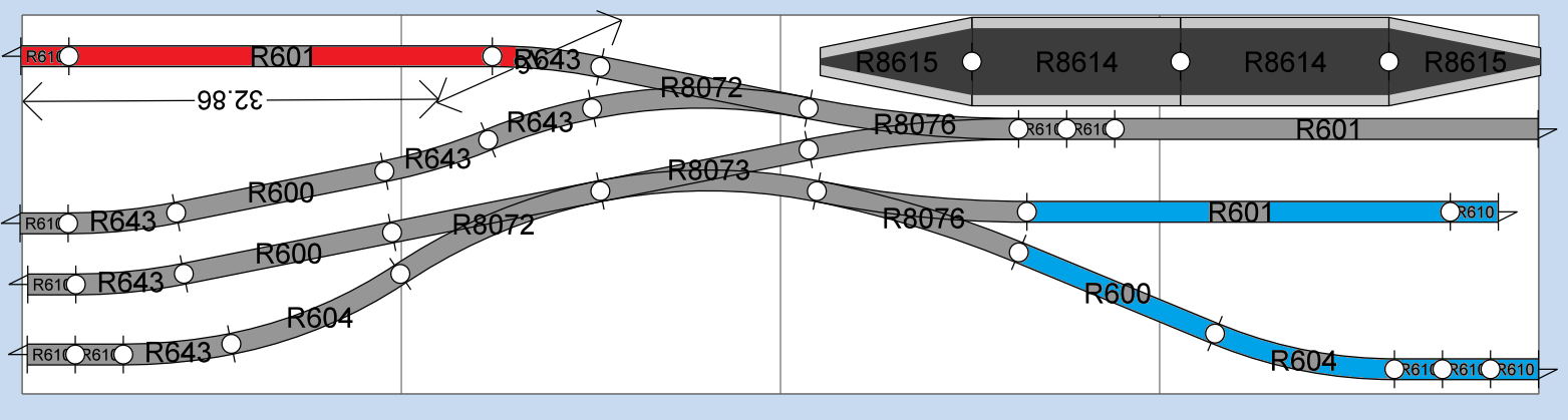
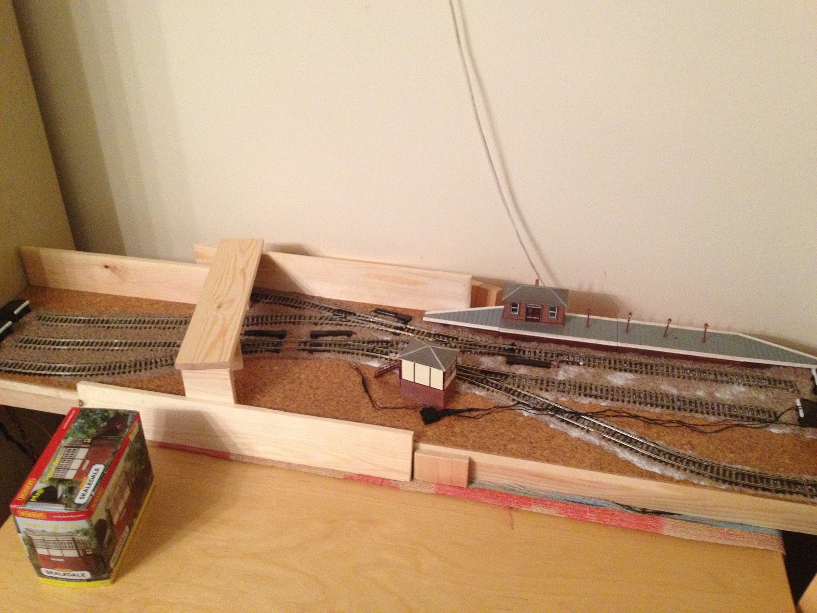
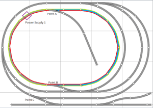
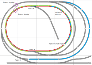
Reminding you of my layout plan, we have: 
  • An out of sight fiddle yard (top right – red track) which at the point of planning will be obscured by a wall and tunnel portal. 
  • A short platform, capable of handling a modern single car Sprinter (i.e. Class 153) and will just about accommodate a two car Pacer (i.e. Class 142). A passenger coach and small steam loco will also fit for bygone eras. Short freight trains can also be accommodated. 
  • A number of sidings all designed to accommodate whatever arrives in the platform. These can either be used to assemble wagons (of any era) or to act as stabling yard for the afore mentioned Sprinter/Pacers. 
  • At this point I’m still reluctant to set an era. Purely because I like the idea of a busy yard with steam trains assembling wagons just as much as I’d like to see DMU’s arriving at some forgotten terminus. But with some clever planning we should be able to make something that would fit plausibly into either category so I can run either scenario.

Most modellers base their layouts loosely on an actual location. (See Tanglewood Common in previous Episodes). It would be easy to set this layout in a rural location. The small station with single platform would work, as would a little freight yard for arriving goods and departing local farm yard produce. A real location would be somewhere like Sudbury or Ongar (pictured above). 
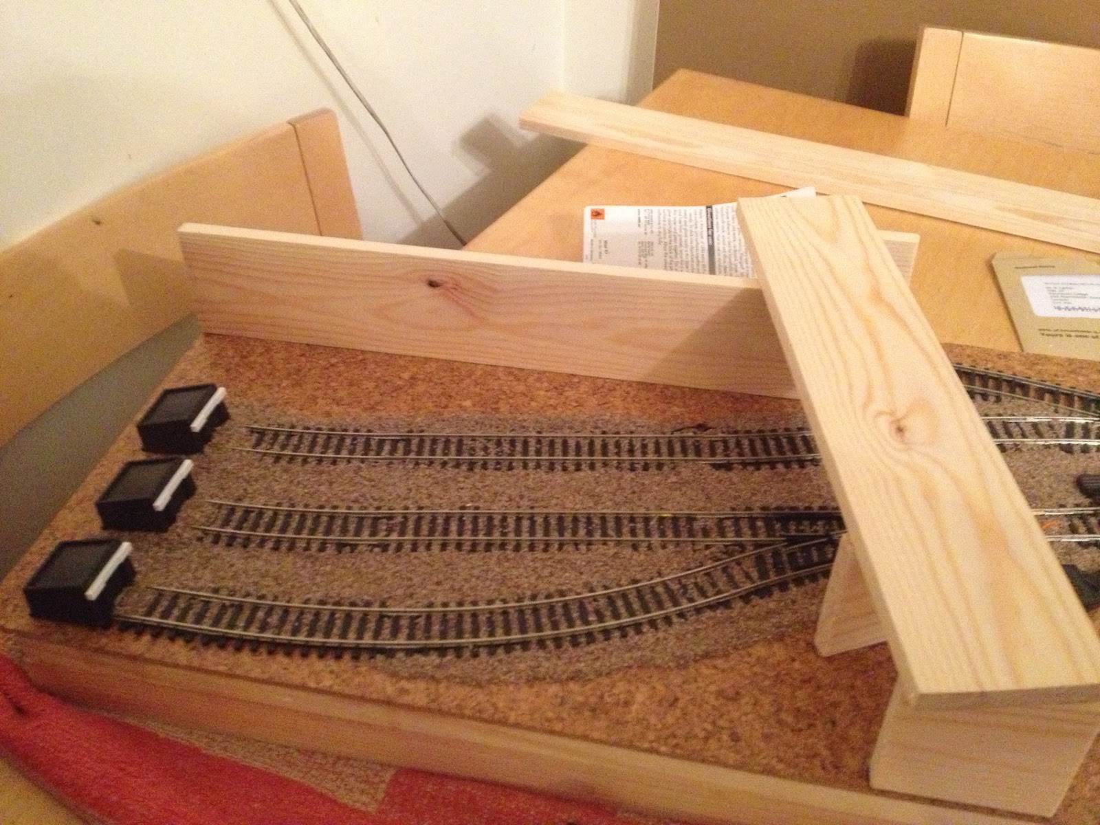
This would however involve landscaping a tunnel for the out of sight fiddle yard. In such a confined space such as this layout this may look odd and indeed prove difficult to pull off. Let’s remind ourselves where I’m actually up to in the design…
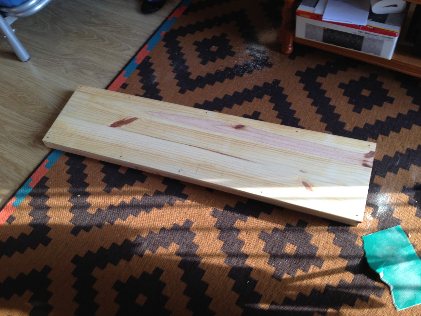
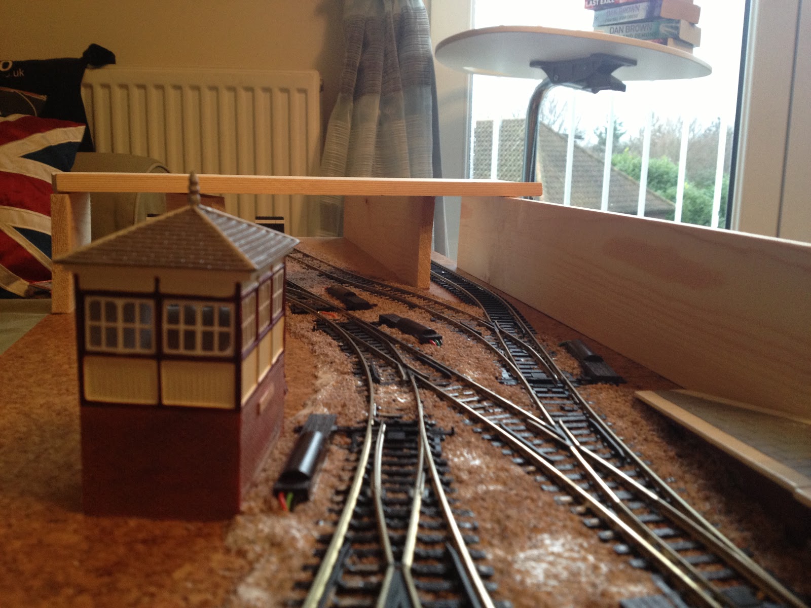
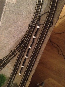
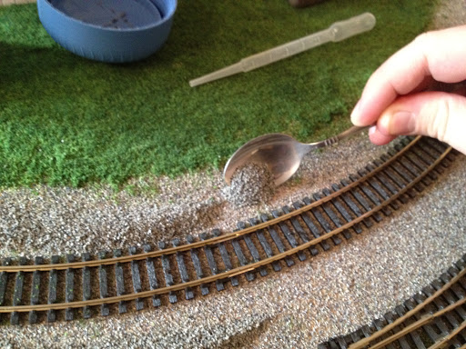
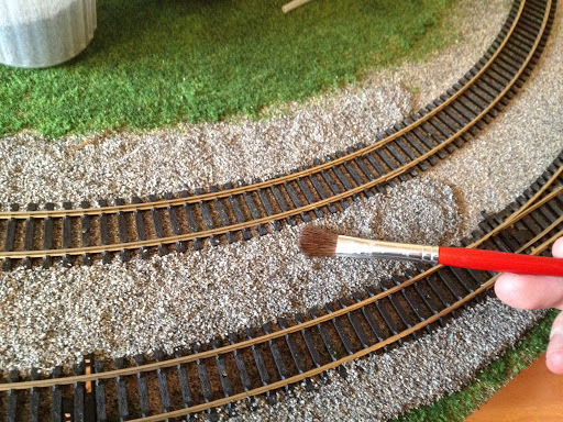
Instead of landscaping a grass bank and tunnel portal, I found it far simpler to use strips of wood that will form walls. A further strip of wood bridges the yard which will later become a road. This both forms the ‘tunnel portal’ effect to the out of sight fiddle yard (at the top) and acts to add an interesting height layer to the layout. 
This changing things. Because the road bridges the yard and creates a tunnel underneath it, we are implying the layout is in a cutting, where the road ‘bridge’ is actually ground level. This coupled with the use of the wood as walls to me implies more of a built up location. Still plausible for passenger services but this time we’ll turn to industrial style traffic for freight rather than farmyard produce.


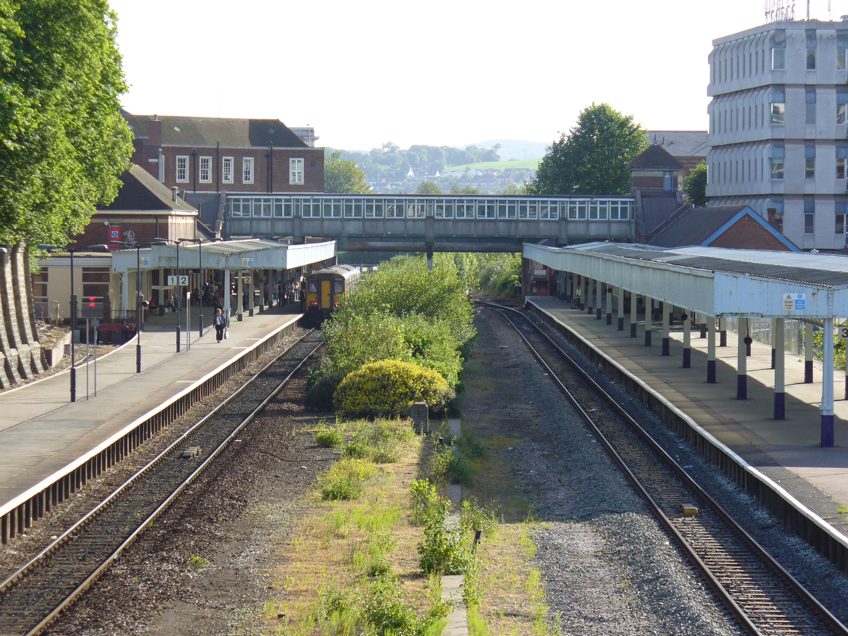
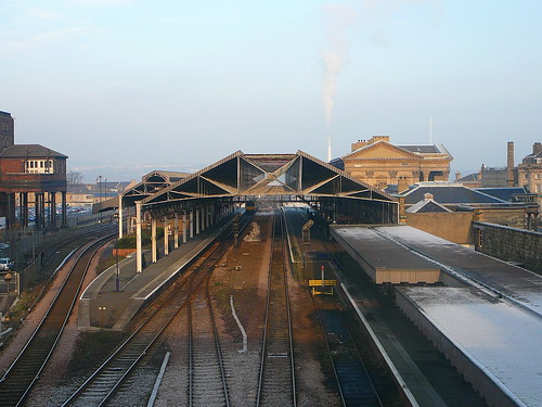
There are no shortage of city stations built into cuttings. Exeter Central (above top), London Liverpool Street and to some extent Huddersfield (above bottom).
But the problem with these stations is that they are quite large, and in most cases are through routes. 
Finding a single platform inner city termini isn’t impossible though.
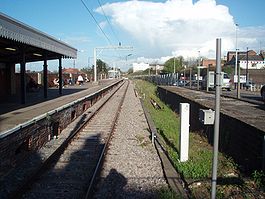
There’s certainly Colchester Town (above top) and Wrexham Central (above bottom). Both of which have managed to stand the test of time despite having much larger through stations in their wake. I like the idea that my station is competing with (in the steam era) or struggling to survive (in the modern era) against larger city stations. These examples are not in cuttings, sure, but we’ve got ideas to work with now. 
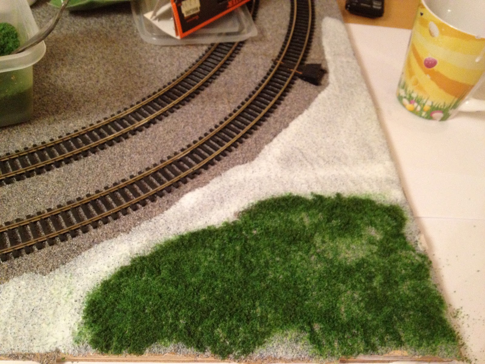
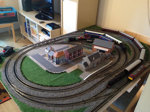
The other thing I want to think of is the architecture of the setting. I’ve already chosen a couple of buildings which you can see in the above picture of my layout from the Hornby Magna range. 

Despite Ashby Magna (of which they are based upon) being in Leicestershire, there is something very ‘Manchester’ about the their red brick facades. 

Anyone from or has ever been to Manchester and it’s surrounding areas will notice that pretty much everything, and I do mean everything, has been built out of red brick. This I have always felt contrasts starkly to the stone structures found in neighboroughing Yorkshire and gives it a very distinct characteristic. Here’s a picture of the abandoned Manchester Mayfield station for example…

Manchester is a good place to pick for a setting. It’s steeped in an illustrious rail history. The first inter-city passenger service in the world started here in 1830 in the form of Manchester Liverpool Road on the Liverpool and Manchester Railway. To cater for Britain’s main industrial city, Manchester Mayfield, Oldham Road, Central and Exchange, all now defunct termini, would have served alongside the now glistening Piccadilly (formally London Road) and the not so glistening Victoria stations. Not to mention Oxford Road, Deansgate, Salford Central and Salford Cresent as well. 
Those of you with a keen knowledge of Manchester’s rail network will realise most of it runs elevated on viaducts through the city. That’s fine, we’ll just have to develop a slightly different back story for our layout that sets it in a cutting rather than on a viaduct. 
So without further ado I present the fictitious location of my layout…
From the south, a line diverges from the viaduct of the former London Midland lines into Manchester Central & through routes to Piccadilly and Yorkshire. It runs northwards over the River Irwell and dips underneath the Manchester to Liverpool line most likely in the place of the A6042. Tunnelling under Ordsall Lane and Chapel Street, the line arrives in the industrialised Blackfirars/Eastern Salford area of the city, just to the north of St Phillip’s Church. The station would probably  sit in the spot the University of Salford’s Centenary Building now occupies. A link line may also exist feeding into Victoria towards the north and east of the city.
I have given the station the name ‘Salford Chapel.’ Perhaps it takes it’s name after Chapel Street just to the south (similar to the theme of naming stations after roads in the city – Oxford Road, Liverpool Road, London Road etc.), or perhaps in reference to St Phillip’s Church… you decide!… It also nicely sits with the theme of both existing Salford stations starting with the letter ‘C’.
In my mind, despite its proximity to others stations, it has survived for providing this area of Salford with a link southwards whereas lines in the area only serve westwards out of the city. 
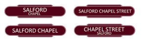
How BR name boards may have looked…
Or on modern Northern Rail branding. 
Image Credits:
Wikipedia (Exeter Central) http://tinyurl.com/a3s684w
Manchester History http://tinyurl.com/bdas3rv

Salford Chapel – Episode 1: A Side Project

As you may be aware I’ve been toying with the notion of a side project, based upon the inspiration of some of Epping Railway Circle’s end to end (or shelf – this will become an important word later on) layouts, like this one…
So far my current layout has developed from concept…
To construction…
To something that really is starting to look rather good.
If you track back to Episode 2, you’ll remember I set myself the task, amongst others, that my layout should be easy to set up and set down. This was, at the beginning, achieved successfully. However as I’ve done more, and added scenery and buildings that can be plopped down the set up and set down time gets a little longer each time. In reality there is never going to be a fast and easy solution to setting up and setting down any model railway that isn’t a permanent fixture. Especially as in my case I’m quite particular in making sure all the trains go back into their correct boxes (must’ve inherited this trait from my Dad) and all the buildings are stacked such that they’re not going to damage each other in storage. 
Now, this isn’t as big a problem as I’m making it sound. I actually quite enjoy the fact it takes a bit of time to get everything set just so. Equally as sad I also enjoy making sure everything is packed away in it’s appropriate place too, right down to putting the boards back in the cupboard; it makes me feel like I’ve successfully achieved some of my targets of this project.

What I will say is, that because setting up and setting down is a now a more lengthy process I feel more obliged to get the layout out when I know I can dedicate a weekend, or a run of days off to its use and continued construction. One day, this will not be a problem when I hopefully don’t have an as busy flat and have maybe some more space at my disposal. It would be really great to have something much smaller that doesn’t need a weekends dedication…

Don’t get me wrong, this is not an abandonment of my original project by any mile, quite the contrary, as I have some updates for you on that front from what I have worked on recently. This side project is also a chance to explore making a more of a model scene, rather than somewhere to enjoy running all the various trains I like. By this I mean there is more potential in a smaller shelf layout to explore things like setting, era and theme. After all, on an end to end layout it’s not possible to set a train going purely for the enjoynment of watching it run. The enjoyment in a shelf layout is different – there’s scope for operational planning, shuffling wagons about mimicking real life scenarios.
So here we go, rather than taking months to tell you where I’m up to on this project, most of the techniques I have already done so rather than taking months to explain where I’m up to, I will update you more swiftly…

Here’s the design. I agonised over this for quite a while, and maybe there is scope for a separate blog of how many versions of this plan I went through until I got to this one…

The dimension is 120 cm x 30 cm, why will become clear shortly.

It will feature:

  • A small terminus station, which could either be a rural location of forgotten inner city branch.
  • A number of sidings and head shunts. These will all comfortably accomodate a 2 car Pacer DMU or a tank loco + coach by design, meaning I can give this either a modern or historical setting, or preferably something neutralish so I can chop and change.
  • An out of sight ‘fiddle yard*’ (the red line) where trains will appear to vanish up the main line and into a tunnel.

*Fiddle yard is a term used by model railwayers to describe a set of sidings or track out of sight from the rest of the layout. They are usually un-landscaped and hidden in such a way to maintain the illusion of a setting for the rest of the model.

A trip to B & Q and I come back with this. It is, rather unsurprisingly, a 120cm x 30cm pine untreated shelf. (Shelf being a key word remember). This will act as my baseboard.

The track fits on it thussly…
You’ll be wondering why these dimensions?
My desk is exactly 120cm long, as is my coffee table (nearly). It’s also relatively small and inoffensive so storage is going to be no problem at all, but it’s going to be easy to move about and I can plonk it in more places when in use.

 
This time I wanted to explore the use of motorised points. Therefore I’ve raised the baseboard up by putting it on a ‘frame.’ And by ‘frame’ I mean two pieces of strip wood. I nailed the shelf to these.
Completed baseboard on frame.
I can confirm that pine will accept track pins with ease, as will it accept drilling: to come later…
I have however elected to lay down some cork on top of the baseboard which will hide the nails of the frame and also provide a uniform surface for everything else going on top.
Some modellers will find proper cork sheets. Me? I’m using floor tiles. They’re even slightly laminated which will later prove helpful when sticking things to it… They’re also rather brilliantly (roughly) 30cm x 30cm meaning I’m not going to have to cut a great deal!
PVA glue (100% as opposed to a mix with water) will do just fine here.
This time, whilst laying the track, I have drilled holes as I go for track power supplies and points. A good tip I picked up on the forums was to pre solder power supply lines to the fishplates, this will help you not melt the sleepers as I did in my other layout…
This partly worked… It would have worked better if I wasn’t using utterly rubbish solder but it did involve snapping off a bit of sleeper from some track which you’ll see in following photos.

Once this was all complete I added some point motors.

Now, I could take up a whole blog talking about point motors. They come in a variety of flavours and costs. Most modellers will opt for something that is fitted underneath the board, some even go the whole hog with wires and pulleys mimicking signalling systems of days gone by.
As this is my first go, I’ve opted for surface mounted point motors. Peco PL-11’s to be precise. They are really simple to fit – simply latch onto the side of your point and nail down. A small hole will be required for the wires to disappear under your board. (Hence the frame). Most modellers will opt for something more discrete but this is my first attempt after all.
Again you can go and get really cheap switches but I’ve elected to get the more expensive Hornby ones. This was in part because they give a much nicer, and more authentic, signal cabin lever experience but partly because they are much easier to wire.
I could go into much more detail, and maybe I will do a dedicated post about the point wiring  at some point, but essentially for PL-11: You connect the red and black wire to the switch. These dictate which way the point sets. You then connect all the green wires (these are your commons) to one side of your power supply. The other side of the power supply feeds power to the switches. In the above picture, this one is brown, but it quite hard to see.  Again, I will properly explain this all at some point. There are also good places to go to explain how to do it… Like here

Rather excitingly, all the points worked straight away! Very pleased with myself.

Wiring takes shape underneath.
Next up it’s time to start adding some ballast. Check out This Episode for a more detailed breakdown.
I’ve used a slightly different colour than before. I’ve also stuck down the platform and buildings here using some super glue.
After another trip to B & Q, I’ve obscured the fiddle yard using some strip wood. I’ve also taken the opportunity to build a bridge for some added scenic interest. (I’m going to talk more about the decisions I’ve made on the landscaping in future blogs).
Another view, the mainline disappearing into the ‘tunnel’ on the right. Cleverly hidden by the strip wood.

And that’s where we’re up to!


Langstead – Episode 11: Powerrrrrrrr

As the great Jeremy Clarkson once said, ‘Powwwweeerrrrrrr.’
Back in’t’day… there was only one way to power your model railway. A good old Analogue potentiometer took care of business. You can go faster. Or you can go slower. One train and one controller per track. Simple. 
More recently however the model railwaying world has been taken a storm by DCC (Digital Command Control). I’m not going to go into detail, because you can catch me chatting about DCC in Side Tracked 1 of this blog, but DCC allows for multiple trains per track, plus an array of extra such as lighting and sound via one control unit. Sounds great, but it is more expensive and you will have to convert your existing locos with special decoder chips.
One day I will invest in DCC and possibly convert some of my older stock but right now we’ll look at a couple of power issues on my good old Analogue layout.
Isolation:
First an issue with Isolation. DCC layouts can support multiple trains on the same track due to given every loco a code and powering that code accordingly. With an analogue layout, you don’t have this luxury and 9 out of 10 times the golden rule is: one train per track/loop and one train per power supply
You can of course, like I have, design your layout to have multiple loops to accommodate additional trains which can be isolated from the power supply and swapped as desired. This works perfectly well for certain point setups…
When Point C and Point D are set in favour of the Outer Loop you are isolating the outside rail of the Inner (Orange) track. Locos must receive power on both rails to work, therefore by setting C and D in this way you have definitely broken part of the circuit on the Inner (Orange) loop and your train doesn’t move. Conversely you can set C and D in favour of the Inner (Orange) loop and this Isolates the Outer Loop allowing for aforementioned train swapage. Forgive me if this is simple stuff but it helps explain the next part a bit better. 
My plan was to deploy a similar tactic for the Blue section of track, isolating a train here allowing A and B to be set to allow access to the centre siding from the Outer Loops. This is essential for maximising stock on the layout. As the following diagram will illustrate this plan was slightly flawed… 
Even with points A and B set in this way the Blue section of track is not isolated. Wherever you place a locomotive on the oval it will still pick up power from ‘Power Supply 1.’ You can check this by choosing a point on the oval and see if the red and green lines end up at the purple box (Power Supply 1). And they always do.
We therefore need to create a break in either* the Red or Green line in the Blue section of track which we want to isolate.
*Remember we only need to break one rail for the locomotive not to be part of the circuit. 
Thankfully – this is painfully simple. 
Carefully lifting up the track I was able to remove both fishplate connections just to the right of ‘Point B.’
This achieves a physical break in the track. Don’t worry though, as long as you are accurate with your nailing (back) down the track is still aligned and this doesn’t affect the running of your trains when you DON’T want to isolate this section.
When you do however, you’ll notice that in the Blue section of track the Red line (rail) is now disconnected from Power Supply 1. 
You can now safely put a train in this section whilst you move another out of the centre siding. 
A similar tactic was also employed just to the right of Point C (above). 
Some modellers will add additional isolation points and purposefully reconnect them via an on/off switch. This gives them the option to turn power on and off to sections of continuous track should they so desire.
This is something for me to consider in the future, but currently it is not required on a layout of this size.
Getting Power To The Track:
The second thing I’ve done that relates to Powweerrrrr isn’t so much an issue but more of a way of making the layout look neater. It does also help in set up/down.
Here was what I was using before…
This is the ‘Hornby Power Clip.’ You plug in your power supply to the points A/B (above) and it slots into the side of your track. This is fine for those starting out, but I find them unsightly, unreliable and restrictive of at which spots on your track they can be slotted into. 
This is how they looked on my layout. I found that once you had a wire plugged into this one (above) on the inner loop, it was encroaching and restricting the loading gauge of trains on the outter loop. Securing the wire from not getting caught up in the trains on both loops was also becoming a problem.


This (above) – killed two birds with one soldering iron. And some wire hooks.
Quite simply – I’ve soldered the wires straight onto the track. Then using wire hooks nailed the wire down to keep them away from trains. Eventually I will paint these black, and I think they will look like quite realistic lineside cabling! (Hopefully no OO scale people will come and steal it…).
I found it easiest to feed wires under track under fishplate joins. 
It may be worth removing a couple of the plastic sleepers where you intend to solder the wire to the track. I found it hard to avoid them melting…. The track is tough though and will accept the heat without buckling. Other modellers will solder the wire to a fishplate first, and then reconnect the fishplates to the track. This avoids being near any melting sleepers when soldering… But this sounded fiddley, so I didn’t bother. 
  
To complete the setup I ran the wires under the join and then along the side of the board. The controllers are then plugged in just out of sight on the right.
Next time I’m going to talk a little bit about adapting points to help reduce derailments. 

Langstead – Episode 10 ½: Layout In Operation 04/11/12

A little video of the layout in operation. Hopefully displaying what the pictures can’t.

Things to note:

  • I’ve added more scenic scatter (the greens and browns) which now covers most of the board. The brown area is intended to be ‘yard access’ from the main streets. I want to add different colour browns at a later date to make this look more realistic.
  • The addition of some denser/’clumpier’ scatter has been added to create the affect of hedge rows. These have also helped separate track bed from grass in a much neater manner. More of this will be added in other areas soon.
  • The gap in scenery at the bottom left of the video, as mentioned in previous Episodes, has been left for a potential level crossing.
  • There is some new cabling shown bottom left. This is a more permanent track power fixture which I will explain in upcoming episodes.
  • Watch out for the de-railing wagon about half way through! And the dodgy camera angle as I try to hide re-alligning it. I’m investigating as to why this occasionally happens.

Langstead – Episode 10: More Ballast

In the last episode I said I’d talk about track power and some isolation issues that I came across, and I will get to this… But first I thought I’d update you on how the fix for the running green flue went. (Last discussed in Episode 7: Playing Sim City Part 1). 
Not well unfortunately. 
The recolouring the track bed with the same colour scatter as the scenic-mat (see above) worked excellently. However the scatter just didn’t take to the board very well and started to flake off. Disappointing, yes, but not the end of the world completely. 
It was always my intention in this project to properly add ballast scatter. In fact, it has already been purchased, hence why in the last Episode I had some spare to make faux wagon loads. The reason I have held back on this plan up until now was I was less confident with a) how well the ballast would stick to the board and b) what I should do about the removable track/board joins
.
At the same time as trying to fix the initial green-running glue I also tested adding some ballast scatter to a small siding to see how well it stuck and what it looked like (My method I will get to..) The result far exceeded my expectations which solves part ‘a.’ Part ‘b’ I was still unsure of but decided to start the ballast process on the rest of the layout regardless. 
There are available, on the magic of the interwebs, a tool that will help spread the ballast evenly.  This looks like it will achieve us excellent results, however it spreads ballast between the sleepers and between the running rails as well as either side. Whilst this will look realistic, at this stage I do not want to add ballast between the running rails. This is purely because I have removable track and what to keep the ‘look’ uniform around the layout. I feel that any ballast between running rails may get stuck in there in the gluing process and then hinder my ability to remove the un-nailed down track needed to split the two base boards for storage.
I will therefore spread the ballast without the tool, and this will also give me a greater degree of control of where I put it. 
So, to get started spoon, pour, lump on some ballast to your layout. I used a small paint brush to spread it about evenly.

Next I added some of the specialist scenic cement seen in previous Episodes. Other modellers recommend the mix of PVA and water but there’s something reassuring about the word ‘cement’ that implies heavy duty sticking quality. I used the pipette method to drop the glue onto the dry ballast. Be very generous with your glue here I’d say. 
Leave this to dry, it will definitely take upwards of 12 hours so don’t be disheartened if you go back to it after 4 and it feels like it isn’t sticking, it will. 
I think it would be possible to leave it there, but to make sure it really is stuck I added a layer of PVA glue over the top which dries clear. This really should help to lock in the individual grains. The PVA layer usually takes a little less time to dry, and again be generous with the helping.
The results look great. I’ve left a few gaps in the ballast at this point – namely the aforementioned removable track sections, which includes the sidings in the centre of the board. I’ve also left out the far edges of the board which are handled in storage frequently as well as a section for a future level crossing.
I can also testify that the ballast has properly stuck as you’ll remember my boards are stacked vertically in storage and I’ve experienced no problems with it coming unstuck. A few lose bits may fall off at first but this is merely excess from the initial scatter. 
The whole process should take a few days. Once it was complete I laid the layout out in full and made sure trains were still running ok. At his point I decided to add in the gaps I’d left around the removeable track. It’s just going to be a case of ‘we’ll see what happens’ as I rig and de-rig the layout over time. I was perhaps a bit more sparing of the ballast in these sections to allow a bit of extra give for the removable track. In other regions you can really get the ballast up and in-between sleepers, here I’ve been less aggressive with coverage. 
As for the sidings, I’ve gone for a slightly different approach and laid ballast over the whole area. In part an experiment to see if I can apply a similar tactic on the mainline in the future.
A good question raised at the end of this is why have I added ballast scatter at all? After all I have the original scenic-mat, in ballast style, at the bottom of all of this gradually getting more and more covered up. Part of the answer was to resolve the issue of the running-green glue. But it’s also in part to the fact I am new at this, so it’s all an experiment in its own right. Whilst the scenic-mat was adequate to start with, I built up the confidence to add in a more realistic look (the ballast scatter) which we initially ruled out as a primary track underlay all the way back in Episode 3. 
So, what I will say is, if/when tackling a similar project from scratch again, I may rethink using the scenic-mat and going straight to the wood with all the scatter – grass and ballast. Ultimately the scenic-mat has been more messy than I thought it would be, both in moving it about and having to chisel some of it off for the roadways. HOWEVER, the good point of having a scenic-mat it is that it has provided a uniform base colour. There may be areas where ballast coverage has been patchy, or maybe the border between ballast and grass is not quite perfect – in these cases instead of wood showing through, the ballast mat shows through. Which is grey. And doesn’t look odd. Modellers may favour paint for the same undercoat effect, but in my case the scenic-mat works just as well.