Langstead – Episode 11: Powerrrrrrrr

As the great Jeremy Clarkson once said, ‘Powwwweeerrrrrrr.’
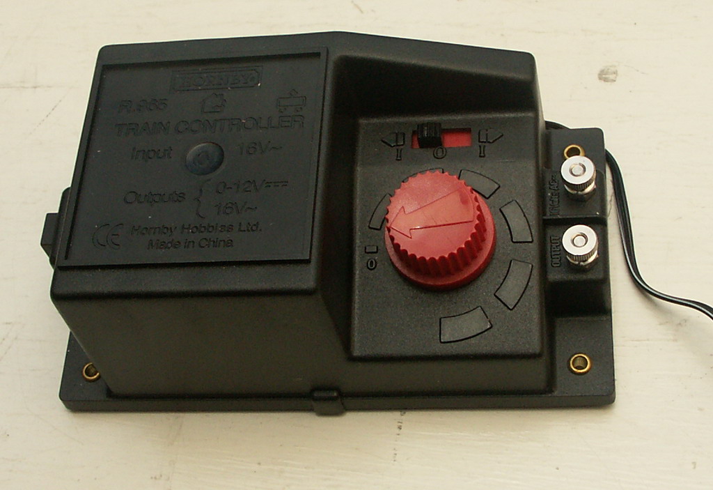
Back in’t’day… there was only one way to power your model railway. A good old Analogue potentiometer took care of business. You can go faster. Or you can go slower. One train and one controller per track. Simple. 
More recently however the model railwaying world has been taken a storm by DCC (Digital Command Control). I’m not going to go into detail, because you can catch me chatting about DCC in Side Tracked 1 of this blog, but DCC allows for multiple trains per track, plus an array of extra such as lighting and sound via one control unit. Sounds great, but it is more expensive and you will have to convert your existing locos with special decoder chips.
One day I will invest in DCC and possibly convert some of my older stock but right now we’ll look at a couple of power issues on my good old Analogue layout.
Isolation:
First an issue with Isolation. DCC layouts can support multiple trains on the same track due to given every loco a code and powering that code accordingly. With an analogue layout, you don’t have this luxury and 9 out of 10 times the golden rule is: one train per track/loop and one train per power supply
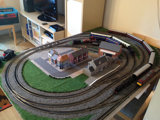
You can of course, like I have, design your layout to have multiple loops to accommodate additional trains which can be isolated from the power supply and swapped as desired. This works perfectly well for certain point setups…
When Point C and Point D are set in favour of the Outer Loop you are isolating the outside rail of the Inner (Orange) track. Locos must receive power on both rails to work, therefore by setting C and D in this way you have definitely broken part of the circuit on the Inner (Orange) loop and your train doesn’t move. Conversely you can set C and D in favour of the Inner (Orange) loop and this Isolates the Outer Loop allowing for aforementioned train swapage. Forgive me if this is simple stuff but it helps explain the next part a bit better. 
My plan was to deploy a similar tactic for the Blue section of track, isolating a train here allowing A and B to be set to allow access to the centre siding from the Outer Loops. This is essential for maximising stock on the layout. As the following diagram will illustrate this plan was slightly flawed… 
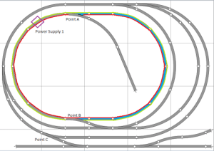
Even with points A and B set in this way the Blue section of track is not isolated. Wherever you place a locomotive on the oval it will still pick up power from ‘Power Supply 1.’ You can check this by choosing a point on the oval and see if the red and green lines end up at the purple box (Power Supply 1). And they always do.
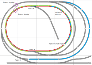
We therefore need to create a break in either* the Red or Green line in the Blue section of track which we want to isolate.
*Remember we only need to break one rail for the locomotive not to be part of the circuit. 
Thankfully – this is painfully simple. 
Carefully lifting up the track I was able to remove both fishplate connections just to the right of ‘Point B.’
This achieves a physical break in the track. Don’t worry though, as long as you are accurate with your nailing (back) down the track is still aligned and this doesn’t affect the running of your trains when you DON’T want to isolate this section.
When you do however, you’ll notice that in the Blue section of track the Red line (rail) is now disconnected from Power Supply 1. 
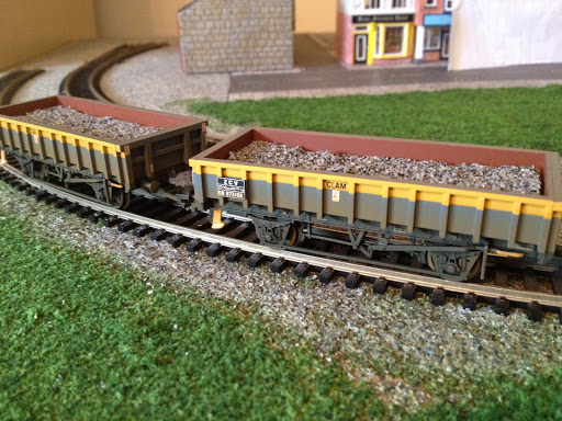
You can now safely put a train in this section whilst you move another out of the centre siding. 
A similar tactic was also employed just to the right of Point C (above). 
Some modellers will add additional isolation points and purposefully reconnect them via an on/off switch. This gives them the option to turn power on and off to sections of continuous track should they so desire.
This is something for me to consider in the future, but currently it is not required on a layout of this size.
Getting Power To The Track:
The second thing I’ve done that relates to Powweerrrrr isn’t so much an issue but more of a way of making the layout look neater. It does also help in set up/down.
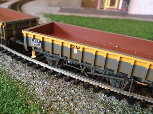
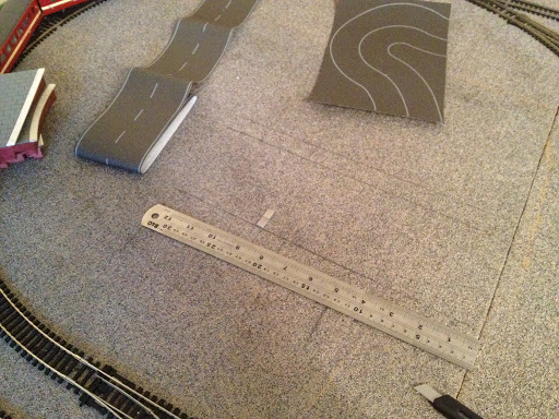
Here was what I was using before…
This is the ‘Hornby Power Clip.’ You plug in your power supply to the points A/B (above) and it slots into the side of your track. This is fine for those starting out, but I find them unsightly, unreliable and restrictive of at which spots on your track they can be slotted into. 
This is how they looked on my layout. I found that once you had a wire plugged into this one (above) on the inner loop, it was encroaching and restricting the loading gauge of trains on the outter loop. Securing the wire from not getting caught up in the trains on both loops was also becoming a problem.


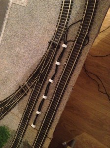
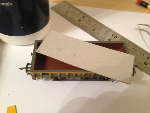
This (above) – killed two birds with one soldering iron. And some wire hooks.
Quite simply – I’ve soldered the wires straight onto the track. Then using wire hooks nailed the wire down to keep them away from trains. Eventually I will paint these black, and I think they will look like quite realistic lineside cabling! (Hopefully no OO scale people will come and steal it…).
I found it easiest to feed wires under track under fishplate joins. 
It may be worth removing a couple of the plastic sleepers where you intend to solder the wire to the track. I found it hard to avoid them melting…. The track is tough though and will accept the heat without buckling. Other modellers will solder the wire to a fishplate first, and then reconnect the fishplates to the track. This avoids being near any melting sleepers when soldering… But this sounded fiddley, so I didn’t bother. 
  
To complete the setup I ran the wires under the join and then along the side of the board. The controllers are then plugged in just out of sight on the right.
Next time I’m going to talk a little bit about adapting points to help reduce derailments. 

Langstead – Episode 10 ½: Layout In Operation 04/11/12

A little video of the layout in operation. Hopefully displaying what the pictures can’t.

Things to note:

  • I’ve added more scenic scatter (the greens and browns) which now covers most of the board. The brown area is intended to be ‘yard access’ from the main streets. I want to add different colour browns at a later date to make this look more realistic.
  • The addition of some denser/’clumpier’ scatter has been added to create the affect of hedge rows. These have also helped separate track bed from grass in a much neater manner. More of this will be added in other areas soon.
  • The gap in scenery at the bottom left of the video, as mentioned in previous Episodes, has been left for a potential level crossing.
  • There is some new cabling shown bottom left. This is a more permanent track power fixture which I will explain in upcoming episodes.
  • Watch out for the de-railing wagon about half way through! And the dodgy camera angle as I try to hide re-alligning it. I’m investigating as to why this occasionally happens.

Langstead – Episode 10: More Ballast

In the last episode I said I’d talk about track power and some isolation issues that I came across, and I will get to this… But first I thought I’d update you on how the fix for the running green flue went. (Last discussed in Episode 7: Playing Sim City Part 1). 
Not well unfortunately. 
The recolouring the track bed with the same colour scatter as the scenic-mat (see above) worked excellently. However the scatter just didn’t take to the board very well and started to flake off. Disappointing, yes, but not the end of the world completely. 
It was always my intention in this project to properly add ballast scatter. In fact, it has already been purchased, hence why in the last Episode I had some spare to make faux wagon loads. The reason I have held back on this plan up until now was I was less confident with a) how well the ballast would stick to the board and b) what I should do about the removable track/board joins
.
At the same time as trying to fix the initial green-running glue I also tested adding some ballast scatter to a small siding to see how well it stuck and what it looked like (My method I will get to..) The result far exceeded my expectations which solves part ‘a.’ Part ‘b’ I was still unsure of but decided to start the ballast process on the rest of the layout regardless. 
There are available, on the magic of the interwebs, a tool that will help spread the ballast evenly.  This looks like it will achieve us excellent results, however it spreads ballast between the sleepers and between the running rails as well as either side. Whilst this will look realistic, at this stage I do not want to add ballast between the running rails. This is purely because I have removable track and what to keep the ‘look’ uniform around the layout. I feel that any ballast between running rails may get stuck in there in the gluing process and then hinder my ability to remove the un-nailed down track needed to split the two base boards for storage.
I will therefore spread the ballast without the tool, and this will also give me a greater degree of control of where I put it. 
So, to get started spoon, pour, lump on some ballast to your layout. I used a small paint brush to spread it about evenly.

Next I added some of the specialist scenic cement seen in previous Episodes. Other modellers recommend the mix of PVA and water but there’s something reassuring about the word ‘cement’ that implies heavy duty sticking quality. I used the pipette method to drop the glue onto the dry ballast. Be very generous with your glue here I’d say. 
Leave this to dry, it will definitely take upwards of 12 hours so don’t be disheartened if you go back to it after 4 and it feels like it isn’t sticking, it will. 
I think it would be possible to leave it there, but to make sure it really is stuck I added a layer of PVA glue over the top which dries clear. This really should help to lock in the individual grains. The PVA layer usually takes a little less time to dry, and again be generous with the helping.
The results look great. I’ve left a few gaps in the ballast at this point – namely the aforementioned removable track sections, which includes the sidings in the centre of the board. I’ve also left out the far edges of the board which are handled in storage frequently as well as a section for a future level crossing.
I can also testify that the ballast has properly stuck as you’ll remember my boards are stacked vertically in storage and I’ve experienced no problems with it coming unstuck. A few lose bits may fall off at first but this is merely excess from the initial scatter. 
The whole process should take a few days. Once it was complete I laid the layout out in full and made sure trains were still running ok. At his point I decided to add in the gaps I’d left around the removeable track. It’s just going to be a case of ‘we’ll see what happens’ as I rig and de-rig the layout over time. I was perhaps a bit more sparing of the ballast in these sections to allow a bit of extra give for the removable track. In other regions you can really get the ballast up and in-between sleepers, here I’ve been less aggressive with coverage. 
As for the sidings, I’ve gone for a slightly different approach and laid ballast over the whole area. In part an experiment to see if I can apply a similar tactic on the mainline in the future.
A good question raised at the end of this is why have I added ballast scatter at all? After all I have the original scenic-mat, in ballast style, at the bottom of all of this gradually getting more and more covered up. Part of the answer was to resolve the issue of the running-green glue. But it’s also in part to the fact I am new at this, so it’s all an experiment in its own right. Whilst the scenic-mat was adequate to start with, I built up the confidence to add in a more realistic look (the ballast scatter) which we initially ruled out as a primary track underlay all the way back in Episode 3. 
So, what I will say is, if/when tackling a similar project from scratch again, I may rethink using the scenic-mat and going straight to the wood with all the scatter – grass and ballast. Ultimately the scenic-mat has been more messy than I thought it would be, both in moving it about and having to chisel some of it off for the roadways. HOWEVER, the good point of having a scenic-mat it is that it has provided a uniform base colour. There may be areas where ballast coverage has been patchy, or maybe the border between ballast and grass is not quite perfect – in these cases instead of wood showing through, the ballast mat shows through. Which is grey. And doesn’t look odd. Modellers may favour paint for the same undercoat effect, but in my case the scenic-mat works just as well. 

Langstead – Episode 9: A Question Of Ballast

It is my hope that the title of this episode will help Moody Blues fans stumble upon this blog by accidently spelling the title of their 1970 chart topping album wrong. Having explained this to you, the pun no doubt becomes a lot less funny, nevertheless in this episode I do intend to answer a Question Justin Hayward never got round to asking: ‘What’s the best way to fill my wagons?’
From the last two episode you will probably conclude that I ‘lost the bottle’ to build my own buildings and elected to buy pre made ones. You can do this with wagon loads – buy pre made, however it is not my intention to completely cheat my way through this project so here’s a little idea I picked up from the excellent www.newrailwaymodellers.co.uk (If you haven’t already visited this site, give it a look in, it offers a lot of advice for beginners like me) on making your own wagon loads.
How Is It that we need to ‘make’ a load?! – I hear you say. Why not just load up with lose scatter?
Yes, this is a cheap, easy and very athletically pleasing solution. However, what if the train derails? What if you accidently knock the wagon? You’re going to create a mess of miniature aggregate all over your layout. Not to mention the extra weight you will be adding to the train…
So here’s an idea to fake it. (OK so a little cheating will be involved today). The principle follows that of buying your own load. Making it look like there’s more contents than there actually is…
Start by measuring out your wagons dimensions and cutting a piece of card to this size. Doesn’t have to be special card, I’ve used a piece of Kellogg’s finest. In fact I’ve glued two together for a bit more rigidity. This will form the base of your load.
Next up, add some smaller pieces of card to the load base. This will help raise the load up to make the wagon look full. 
A work in progress….
Add some glue and go nuts with some aggregate. It’s Up To You what you use here, I’ve gone with some spare ballast (hence title) scatter which I intend to use in the near future for my layout. You may also want to add a layer of glue over the top almost immediately using my afore mentioned pipette method to really help the ballast stick.
Go ahead and leave it to set/dry over night or over an equally large period of time.
And here we have the wagons ‘full’ with ballast load. I found I had to trim the card again as it must’ve soaked up the quantity of glue I used like a sponge. Actually, I say ‘full’ – it could benefit from being raised up a tad – but that’s the beauty you can adjust as required whereas purchasing readymade alternative won’t allow this (easily).
You get The Ballance of low weight, cheapness (It only cost me £1.99 for a big ol’ bag of ballast scatter – of which I’ve used only a very tiny amount here) and something which looks good. In fact I think this looks better than a bought option as, well it’s real aggregate!
In the next Episode ‘Every Good Boy Deserves Fish Plates’ we’ll look at a an issue regarding track power and isolation…

Langstead – Episode 8: Playing Sim City: Part 2

Last time I talked about buildings and my town/village scene. These need to inevitably be accompanied by some roads.
As per usual there’s a range of options… 
We could paint the road on. This option is preferred by many modellers and looks very good. However my predicament is that the entire board is covered with ballast-mat and whilst stripping it off in patches is an option; stripping it down to the bare wood again is going to be difficult. 
We could opt for a tarmac coloured scatter, but these may provide the same or similar texture as the green (grass) and I don’t think that would feel right…
…So I’ve found some of this! It’s sticky back road-in-a-strip from Gaugemaster and it’s pretty cheap. 
I’ve also got myself some of these! Little sticky paving slabs.
First job is to mark out where you want your road to be constructed.
Then strip back the ballast-mat with a chisel. The goal is to get as much of the wood showing as possible but it is OK if it’s not 100%. We are going to stick over it after all! Just as long as it’s as smooth as you can manage!
This was both messy and irritating but eventually the area looked something like this!

The paving slabs are sticky – but with the stuck on walls of my old plastic buildings fresh in my mind, it’s likely that overtime they will become unstuck. Also don’t forget they’re not going down onto a completely dust free and even surface!
I therefore will lay them out first to get an idea of how they look and then glue them down with PVA. (This is actually recommended by Metcalfe). 

The road is opened! (I wish they’d finish the roadworks on the M1 this quickly…). Looks good actually!
Now that I’m happy with the way it looks and where it is, I can expand as necessary to a larger town plan. I used tweezers to help me lift and replace the tiles. It took all day but the result is worth it.
Here is a work in progress shot. The problem with planning out the town is I’ve had to do it on quite an ad-hoc basis. It’s difficult to quite judge the size of buildings in the shop, but hopefully I’ve left room for future additions.
I’m also going to future proof the layout by not modelling heavily over the gap in the two boards. i.e. keeping roads at 90 degree angles and not continuing on complex scenery. This should theoretically allow me to one day add a 3rd board in the middle to extend the layout outwards… but this is way off in the future… 
At present I’m waiting for things to dry so more pictures coming soon!